12
A01-00119 Rev. B
Installation
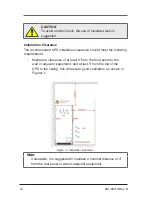
Step 1 Determine the UPS location in accordance with all installation
recommendations
(see 3.4 Installation Clearance)
and UPS
size
(see A Technical Specifications).
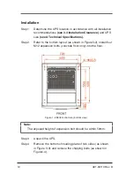
Step 2 Refer to the bottom layout (as shown in Figure3-2), install four
M12 expansion bolts (concrete floor only) into the floor.
Note:
The exposed height of expansion bolt should be within 50mm.
Step 3 Unpack the UPS.
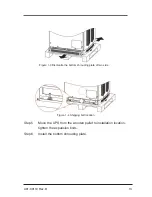
Step 4 Remove the bottom shrouding plate of two sides (as shown
in Figure 3-3) and remove the shipping bolts (as shown in
Figure1-4).
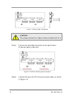
Figure 1-2 Bottom structure (bottom view)
Summary of Contents for Powervar 3400 Series
Page 1: ...3400 Series UPS User s Manual 80 100 125kVA ...
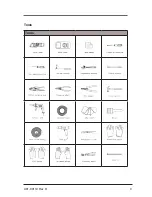
Page 9: ...9 A01 00119 Rev B Tools Tools ...
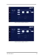
Page 26: ...26 A01 00119 Rev B Figure 2 5 Normal System operation Figure 2 6 System on battery ...
Page 64: ...64 A01 00119 Rev B 9 0 PRODUCT DRAWINGS ...
Page 65: ...65 A01 00119 Rev B ...
Page 66: ...66 A01 00119 Rev B ...
Page 67: ...67 A01 00119 Rev B ...


