background image

52

A01-00119 Rev. B

3.1.4 Start Load

Step 1  Confirm the running status of UPS according to the indicator 

light on panel. When lights indicate that UPS is operational in 

normal mode or battery mode, the UPS can now supply output 

power for loads.

Step 2  Once the UPS has been operational without load for 10min, 

turn on loads in sequence: larger load to smaller load.

3.1.5 Shut Down UPS

Please perform the following steps to shut down the UPS.

Step 1  Disconnect the applied load.

Before disconnecting the load, please ensure that the load is not in use.

Step 2  Shut down the inverter system.

Press the OFF combination buttons on the panels for 1S, the inverter 

will turn off. This operation also can be performed through touch screen. 

The DC bus can store energy for up to 10 minutes after shutdown, so 

caution must be taken when servicing this equipment.

Step 3  Disconnect the external battery input switch, including the 

UPS’s input switch (BATTERY), battery cabinet input switch 

and other external battery input switches.

Step 4  Open the bypass input (if used).

Summary of Contents for Powervar 3400 Series

Page 1: ...3400 Series UPS User s Manual 80 100 125kVA ...

Page 2: ...on and Safety 3 2 0 Installation 8 3 0 Touch Screen Operation 22 4 0 System Operation 50 5 0 Maintenance 53 6 0 Troubleshooting 54 7 0 3400 Series Specifications 59 8 0 3400 Series Warranty 61 9 0 Product Drawings 64 TABLE OF CONTENTS ...

Page 3: ...me for today s sensitive electronic systems Together these products prevent power disturbances from destroying degrading or disrupting system operations AMETEK Powervar is a global provider of power management solutions headquartered in Waukegan Illinois with international sales and distribution offices in Swindon United Kingdom Toronto Canada Mexico City Mexico and Germany Technical Support If af...

Page 4: ...the UPS or within this manual to alert you to important information Please familiarize yourself with these symbols Risk of Electric Shock Observe the warnings associated with the risk of electrical shock CAUTION HOT SURFACE Do not touch Risk of burn hazard CAUTION REFER TO OPERATOR S MANUAL Refer to operator s manual for additional information such as specific operating and or maintenance instruct...

Page 5: ...contact your local recycling refuse or hazardous waste center Information of Special Note Specific handling or operational instructions may apply Phase This is the electrical symbol for the word phase Recycle Equipment or components are made of recyclable material please contact your local recycling center for proper disposal ...

Page 6: ...e operating the UPS or connecting any load equipment please ensure the UPS is connected to a properly grounded electrical supply 2 This UPS has dangerously high voltages on both its input and output connections Contact with these voltages may be life threatening 3 Please do not disassemble the covers There is a risk of electric shock 4 In an emergency immediately turn off the circuit breaker for t...

Page 7: ...nsult with the manufacturer 9 The UPS has an internal EMI filter for purposes of enhancing electromagnetic compatibility with the input mains supply This filter produces leakage current to earth on the input mains When selecting a circuit breaker for the branch circuit supplying power to the UPS ensure that the breaker selected is not an ELCB type circuit breaker that detects earth leakage current...

Page 8: ...happy to take the appropriate action Be sure and save all shipping paperwork Check the packing list to ensure that all peripherals are accounted for and correct for the application If there is any discrepancy make notations and contact your Powervar Representative immediately Environment The final UPS installation location should meet the following requirements The temperature and humidity should ...

Page 9: ...9 A01 00119 Rev B Tools Tools ...

Page 10: ...following requirements Maintain a clearance of at least 3 from the front panel to the wall or adjacent equipment and at last 3 from the top of the UPS to the ceiling this will ensure good ventilation as shown in Figure1 1 Note If allowable it is suggested to maintain a minimal distance of 4 from the rear panel to wall or adjacent equipment Figure 1 1 Installation clearance ...

Page 11: ...abinet connection conductors please refer to Table1 1 and Table1 2 Table 1 1 Cable selection Model Current A Input Output Phase Conductor Grounding Conductor Size AWG 80kVA 96 1 6 100kVA 120 1 0 6 125kVA 150 3 0 6 Table 1 2 Selection for battery cables Model Battery Quantity Input Output Phase Conductor Grounding Conductor Size AWG 80kVA 40 225A 4 0 100kVA 40 300A 350 MCM 125kVA 40 350A 500 MCM Ba...

Page 12: ...cations Step 2 Refer to the bottom layout as shown in Figure3 2 install four M12 expansion bolts concrete floor only into the floor Note The exposed height of expansion bolt should be within 50mm Step 3 Unpack the UPS Step 4 Remove the bottom shrouding plate of two sides as shown in Figure 3 3 and remove the shipping bolts as shown in Figure1 4 Figure 1 2 Bottom structure bottom view ...

Page 13: ...5 Move the UPS from the wooden pallet to installation location tighten the expansion bolts Step 6 Install the bottom shrouding plate Figure 1 3 Dismantle the bottom shrouding plate of two side Figure 1 4 Shipping bolt location ...

Page 14: ... of batteries 1 1 3 Installation CAUTION The installation and maintenance of the external battery cabinet s should only be performed by factory authorized service technicians The installation steps for the external battery cabinet s are as follows Step 1 Install the missing cable removed for shipping per battery cabinet manufacturer instructions CAUTION Before making any connections please make su...

Page 15: ...is greater than 50 from the UPS or the user has specific safety requirements an additional DC disconnect may be required Please consult Powervar for recommended sizing of this equipment Electrical Connection 1 1 5 UPS Wiring The input output conductors should be connected in accordance with all applicable national and local codes CAUTION When making the conductor connections please ensure that sol...

Page 16: ... marked by A B C Step 2 Connect the grounding conductors to the ground post Protective earth of the UPS Step 3 Connect the input of UPS to mains by input cables as shown in Figure 1 8 Figure 1 5 Wiring copper bar diagram Figure 1 6 Protective earthing ground diagram ...

Page 17: ...quence is wrong please correct before going any further 1 1 6 Wring for Series Redundant System The wiring method for a series hot standby system is as follows Step 1 Open the front door of the UPS remove the terminal cover to expose the battery AC input bypass and AC output terminals as shown in Figure 1 9 Figure 1 7 Wiring diagram Figure 1 8 Wiring copper bar diagram ...

Page 18: ... the input phase sequence is wrong please correct before going any further Step 3 Connect the grounding conductors to the ground post Protective earth of the UPS The DB9 connector is located in the upper right hand corner of the interconnect panel It serves as the connection port for RSD232 or RS485 protocol Figure 1 9 Wiring of series hot standby system Figure 1 10 Protective earthing ground diag...

Page 19: ...S remotely Definition for RS232 pins DB9 RS232 485 6P RXD of UPS DB9 RS232 485 7P GND DB9 S232 485 9P TXD of UPS 1 1 8 RS485 Communication The RS232 RS485 communication port is located in the rear of the device It supports remote communication It has the capability for remote monitoring of input voltage frequency output voltage frequency load etc of the UPS and it can also power on off the UPS rem...

Page 20: ... Communication The dry contact communication board is as shown in figure 1 11 The input and output dry contact has 8 channels each For each channel there are 8 options The options are as follows Figure 1 11 Dry contact communication board ...

Page 21: ...Output dry contact Online Operation Load on Inverter Bypass Operation Load on Bypass Redundant Bypass Operation Dedicated For SKRU Battery Operation Battery Low Voltage Programmable Default 420VDC Battery Shutdown Transfer To Bypass Or Dropped Load Overload UPS General Alarm Major Fault Summary Alarm Warming Minor Event Summary UVR Under Voltage Release 24VDC Bypass Abnormal Async Operation Bypass...

Page 22: ...a user can easily browse the input output load and battery parameters of UPS to get the current function and alarm status information of UPS The touch screen can also provide an historical alarm data log which will provide a reliable basis for fault diagnosis Menu Structure of Touch Screen The menu tree of the touch screen shows the function for inquiry and setting The menu structure is as shown i...

Page 23: ...23 A01 00119 Rev B Main Page It will enter system monitoring main page after powering on as shown in Figure 2 2 Figure 2 1 Menu structure of the touch screen ...

Page 24: ...page The meaning of each icon on the main page is as follows System bypass input information System mains input information Battery information System output information Information Status inquiry System settings Alarm inquiry Audible Alarm control Power on off Figure 2 2 Main page ...

Page 25: ...e working status and energy flow on the main page shows the running status of the system The energy flow of each mode of operation is as follows Figure 2 3 Rectifier System startup Figure 2 4 Batteries are connected and the rectifier is started ...

Page 26: ...26 A01 00119 Rev B Figure 2 5 Normal System operation Figure 2 6 System on battery ...

Page 27: ...27 A01 00119 Rev B Figure 2 7 System on bypass Rectifier off Figure 2 8 System on bypass rectifier on ...

Page 28: ...0119 Rev B System Fault The left icon flashes Press indicator to enter current fault page as shown in Figure 2 10 Figure 2 9 System maintenance bypass output Figure 2 10 Protection for fault and with no output ...

Page 29: ...ting press icon it will turn to shutdown confirmation page as shown in Figure 2 12 when system is shutting down press icon it will turn to startup confirm page as shown in Figure 2 13 Figure 2 11 Current fault status information Figure 2 12 Press OK to power the system off ...

Page 30: ...m returns to normal the icon will turn to gray The buzzer can be active again by pressing the icon When in this state if any new fault occurs the buzzer will sound again Monitoring Function 2 1 4 Bypass Information On main page press icon the screen displays the line voltage frequency and loop status of current system bypass input as shown in Figure 2 14 Figure 2 13 Press OK to power system on ...

Page 31: ...main page press icon the displayed information is as shown in Figure 2 15 The screen displays the line voltage line current frequency and loop status of current system input supply Figure 2 14 Bypass information Figure 2 15 AC Input supply information ...

Page 32: ... Rev B 2 1 6 Battery Information On the main page press icon it will show the battery information as shown in Figure 2 16 Figure 2 17 Figure 2 18 Figure 2 16 Battery information 1 Figure 2 17 Battery information 2 ...

Page 33: ...splay the charging current discharging current according to battery status automatically 2 1 7 Output Information On the main page press icon it will show the system output information including phase voltage phase current frequency apparent power active power and load percentage as shown in Figure 2 19 and Figure 2 20 Figure 2 18 Battery information 3 ...

Page 34: ...34 A01 00119 Rev B Figure 2 19 System output information 1 Figure 2 20 System output information 2 ...

Page 35: ...password for the general user the initial password is 123456 for authorized service personnel the password is 121212 the setting screen will appear as shown in Figure 2 22 General user can look up each system parameter but it is read only only authorized service personnel can look up set each parameter Figure 2 21 Login interface ...

Page 36: ...ystem Manage to enter system manage interface specific parameters are as shown in Figure2 23 Press the switchover button to change parameters The setting range of mains voltage upper threshold is 10 15 20 Figure 2 23 System management page Figure 2 22 Parameter setting interface ...

Page 37: ...5 10 ECO mode on off ECO voltage upper threshold 5 10 ECO voltage lower threshold 5 10 N x Warning Only for display After changing the parameter it is necessary to press button to save the setting If the setting save is successful there will be a icon at the right side of the parameter as shown in Figure2 24 if the setting save is unsuccessful there will be a icon at the right side of the paramete...

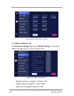
Page 38: ...ge press Battery Manage it will enter battery manage page as shown in Figure 2 26 Equalizing charge voltage V 12 500 14 500 Floating charge voltage V 12 500 14 000 Equal to float charge Delay min 0 180 Figure 2 26 Battery management Figure 2 25 Unsuccessful save setting ...

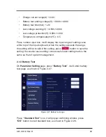
Page 39: ... top of the input keyboard when the setting exceeds the range the setting will be invalid After setting press button to save the setting Successful save setting unsuccessful save setting mark is the same as that of system management 2 1 3 Battery Test On Parameter Setting page press Battery Test it will enter battery test page as shown in Figure 2 27 Press Standard Test icon it will popup confirmi...

Page 40: ...window press OK button to start deep test as shown in Figure2 29 During battery testing if you need to stop testing you can enter battery test page and press Cancel button to cancel battery test as shown in Figure 2 30 Figure 2 29 Deep test Figure 2 28 Standard test ...

Page 41: ...ing On Parameter Setting page press Dry Contact Setting it will enter dry contact setting page as shown in Figure 2 31 After setting press button to save the setting Successful save setting unsuccessful save setting mark is the same as that of system management Figure 2 30 Cancel battery test Figure 2 31 Dry contact setting ...

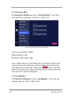
Page 42: ...x it will display the input range of setting value at the top of the input keyboard when the setting exceeds the range the setting will be invalid After setting press button to save the setting Successful save setting unsuccessful save setting mark is the same as that of system management 2 1 6 Log Manager On Parameter Setting page press Log Manager it will enter log manager page as shown in Figur...

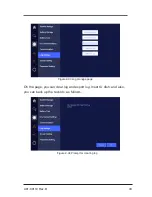
Page 43: ...43 A01 00119 Rev B On the page you can clear log and export log Insert U dish and also you can back up the records as follows Figure 2 33 Log manage page Figure 2 34 Prompt for clearing log ...

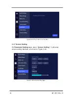
Page 44: ...119 Rev B 2 1 7 Screen Setting On Parameter Setting page press Screen Setting it will enter screen setting interface as shown in Figure 2 36 Figure 2 35 The U dish is not inserted Figure 2 36 Screen setting page ...

Page 45: ...g page press Password Setting it will enter password setting page The current user s password can be changed only as shown in Figure2 37 The password is 1 to 6 digit Arabic numerals After filling in new password press Save button to save the setting Information Inquiry Press icon to enter information inquiry page The related information is as shown in Figure 2 38 Figure 2 37 Password setting ...

Page 46: ...press Work Status it will enter work status page as shown in Figure 2 39 Note If the battery is not connected battery status will show as when operating as a single module the parallel wire status will show as Figure 2 38 Information inquiry page Figure 2 39 Work status ...

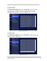
Page 47: ...on it will enter event log page The page records the historical fault and alarm information of the system as shown in Figure 2 40 2 1 3 User Log On Information Inquiry page press User Log it will enter user log page as shown in Figure 2 41 Figure 2 40 Event log Figure 2 41 User log ...

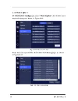
Page 48: ...ormation Inquiry page press Wave Capture it will enter wave capture list page as shown in Figure 2 42 Press the wave capture time it will enter the following page as shown in Figure 2 43 Figure 2 42 Wave capture list Figure 2 43 Wave capture page ...

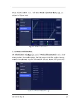
Page 49: ...2 44 2 1 5 Product Information On Information Inquiry page press Product Information icon it will enter product information page the first page shows the product name model manufacturer contact information etc as shown in Figure 2 45 Figure 2 44 Wave capture detail Figure 2 45 Product information page ...

Page 50: ...between phase conductors and ground earth 3 Measure the AC voltage of UPS 1 s mains input on the input terminal AC INPUT The measured voltage of AC input should be within 384V 552VAC 4 Check and measure DC voltage at the battery breaker before closing Double check DC polarity at the UPS terminals before closing battery breaker Failure to do so can cause catastrophic damage and such damage will not...

Page 51: ...sure that the load is within the capacity of the UPS Do not use the On Off function of the UPS to turn on off your load If UPS hasn t been in use for a long period of time the operational prechecks will need to be repeated Operation 3 1 3 Start UPS Please perform the following steps to start the UPS Step 1 Apply AC to the UPS Step 2 Close input supply breaker or disconnect If AC supply is within s...

Page 52: ...hut down the UPS Step 1 Disconnect the applied load Before disconnecting the load please ensure that the load is not in use Step 2 Shut down the inverter system Press the OFF combination buttons on the panels for 1S the inverter will turn off This operation also can be performed through touch screen The DC bus can store energy for up to 10 minutes after shutdown so caution must be taken when servi...

Page 53: ...ironment clean and avoid dust or chemical contamination of UPS 4 1 Periodic Preventative Maintenance To improve the efficiency and reliability of the UPS system please perform the following preventative maintenance operations every 3 months Visually examine the input and output terminals to ensure solid connections Visually examine the fans to confirm working status Be aware of foreign materials c...

Page 54: ...within the rated range 2 The touch screen displays wrong phase sequence the buzzer beeps continuously AC input phase is wrong Change the phase sequence of rectifier s mains input wires Generally it only needs to change two phases among L1 L2 L3 3 The inverter does not operate normally and the buzzer beeps continuously The rectifier is not completely started the buzzer beeps continuously and batter...

Page 55: ...ins normal 7 The LOAD indicator is on in red The output of UPS is overloaded Decrease the load 8 When power on normally it cannot output normally Check whether the bypass inverter SCR drive board is fault Call for service 9 Communication abnormal Communication wiring not complete Check wiring The communication software is not successfully installed Install the software correctly The setting for co...

Page 56: ...onnected 3 After starting the UPS can output 480V AC power but the UPS works in bypass status The load capacity exceeds the rated output capacity It is necessary to decrease load or use a UPS with bigger output capacity If it is temporary bypass caused by starting the load and can recover automatically that is normal 4 After starting the UPS output normally but once starting the load the UPS stop ...

Page 57: ...UPS start to work for a while the buzzer beeps intermit tently The voltage of grid is too low and the UPS works in battery inverting status finally it causes the battery low voltage protection 7 When mains normal the UPS outputs normally when mains failure the UPS is without output Battery fault or the battery group is serious damaged Charger fault The charging for battery cannot be done which cau...

Page 58: ... single unit fault When the single unit fault it is necessary to close the power supply of UPS by OFF button on the panel If necessary close the user load and disconnect the input output switch of UPS which is to avoid further damage of the UPS Emergency remedy for the fault of UPS 1 and UPS 2 in series backup system When the UPS 1 of the series backup system fault it is necessary to close the pow...

Page 59: ...50 60Hz 34125 125 125 50 60Hz System Input Converter Operating Input Voltage 480VAC operating window 384 552VAC Nominal 15 20 3 Phase 3 wire Frequency Range 5Hz Input Current THD 1 100 load 2 50 load Input Power Factor 99 100 load 98 minimum 50 load Battery Voltage 480VDC Nominal 40 batteries x 12V Converter Walk in Time 20 Seconds System Input Bypass Nominal Input Voltage 480VAC 3Phase 4 Wire Inp...

Page 60: ...ulation 50 60Hz 01 free running Output Voltage Harmonic Distortion Less than 1 linear load0 Less than 2 with a crest factor of 2 5 to 1 Output Overload Capacity 300 for 240ms 125 for 10min OR 150 for 60 seconds Voltage Transient Response 1 for a 100 step load Environmental Efficiency 100 load Up to 96 3 Operating Ambient Temperature 0 to 40 C no derating required Storage Temp non operating 20 to 6...

Page 61: ...ervice Providers this warranty will include at Powervar s sole discretion on site service in the USA or specified countries or Powervar depot service For Products sold by Powervar to its non USA based Business Partners Distributors and Service Providers this warranty is limited to parts only worldwide See the Limitations of Warranty section for additional limitations exclusions Contact Powervar fo...

Page 62: ...that are continuously connected to AC mains power except during utility power outages Products that are regularly and intentionally disconnected from AC mains power will experience battery discharge charge cycles that are potentially far more numerous than those for which the battery was designed As a result Products used in such applications will experience substantially reduced battery life Ther...

Page 63: ...use of their Products in life critical applications By extension Powervar must adhere to the same business policy and does not recommend the use of our Products in life critical applications Disclaimer Powervar Products are not designed intended authorized tested or UL Listed for use in systems intended to support or sustain life or for any other application in which the failure of a Powervar Prod...

Page 64: ...64 A01 00119 Rev B 9 0 PRODUCT DRAWINGS ...

Page 65: ...65 A01 00119 Rev B ...

Page 66: ...66 A01 00119 Rev B ...

Page 67: ...67 A01 00119 Rev B ...

Page 68: ...nc USA Address 1450 Lakeside Drive Waukegan IL 60085 1 800 369 7179 P 847 596 7000 F 847 596 7100 Europe Asia Address Unit 5 Birch Kembrey Park Swindon Wilts SN2 8UU UK P 44 1793 553980 F 44 1793 535350 Mexico Address Camino a la Montana No 178 101 PB4 Fracc Industrial La Perla 53340 Naucalpan Edo De Mexico P 52 55 5363 5448 ...

Reviews: