45
98-0155 Rev. C
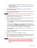
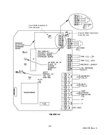
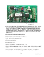
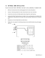
4. The control system for the RO3X ships with resistor R10 (see above) that can be identified
by its color bands (Red-Violet-Red-Gold). If your feed water conductivity exceeds 1,000
µ
S/cm, you may want to change out the resistor in the R10 position with a replacement
resistor, provided by AmeriWater. This replacement resistor can be identified by its color
bands (Blue-Grey-Red-Gold). Alternatively, if you have an ohm-meter, the original resistor
can be identified by its resistance value of 2.7 kΩ; the replacement resistor’s resistance
value is 6.8 kΩ.
5. Remove the R10 resistor with needle nose pliers.
6. Move the replacement resistor to the R10 position.
7. Save the R10 resistor somewhere safe.
8. Close RO controller door.
9. Re-apply power to RO.
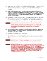
10. Go into setpoints in the controller (Ref. Section 10.1).
11. Change the C2 Range setpoint to meet your needs. C2 Range setpoint 5 is 0-2500, 6 is 0-
5000.
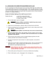
12. Once the setpoint has been changed, then you need to calibrate the units by taking a
sample of the permeate water and testing it with a calibrated conductivity meter.
Summary of Contents for MRO3Z
Page 2: ...98 0155 Rev C ...
Page 5: ...98 0155 Rev C ...
Page 13: ...8 98 0155 Rev C MRO7Z and MRO8Z CONFIGURATION SHOWN BELOW Figure 3 2 ...
Page 15: ...10 98 0155 Rev C 3 2 INTERNAL CABINET TOP AND SIDE VIEW Figure 3 3 ...
Page 16: ...11 98 0155 Rev C 3 3 INTERNAL CABINET TOP AND SIDE VIEW CONT Figure 3 4 ...
Page 18: ...13 98 0155 Rev C 3 4 ELECTRICAL DIAGRAM AND FIELD WIRING Figure 3 5 ...
Page 19: ...14 98 0155 Rev C Fig Figure 3 6 ...
Page 20: ...15 98 0155 Rev C Figure 3 7 ...
Page 21: ...16 98 0155 Rev C 3 5 FLOW DIAGRAMS Figure 3 8 ...
Page 22: ...17 98 0155 Rev C Figure 3 9 ...
Page 23: ...18 98 0155 Rev C Figure 3 10 ...
Page 24: ...19 98 0155 Rev C Figure 3 11 ...
Page 25: ...20 98 0155 Rev C Figure 3 12 ...
Page 26: ...21 98 0155 Rev C Figure 3 13 ...
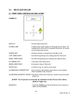
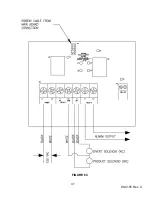
Page 46: ...41 98 0155 Rev C FIGURE 6 3 ...

