22
98-0155 Rev. C
4.0 MROZ STARTUP & OPERATION
4.1 CAUTION
The Operations Manual should then be kept near the system and used as a reference
and troubleshooting guide.
Follow all safety procedures for the facility and company for which all work is being
performed.
CAUTION:
No person should attempt to operate or service the MROZ without
Prior authorization or instruction from your medical facility director.
WARNING: This Reverse Osmosis System (RO) contains a preservative solution to
prevent microbiological growth and freezing. Discard all product water for
at least two hours of operation before placing the RO in service.
1. The MROZ unit needs to be provided with 2 electrical sources with the following
requirements:
a. Electrical source for the controller
i. Single Phase, UL Listed, 3 Conductor type, Hospital grade receptacle
with Ground Fault Indicator (GFI)
ii. Rated for 125VAC, 20 AMP, 2.5KVA, 60 Hz
b. 208/230VAC Models
i. Electrical source for the pump
1. UL listed, Lockable, NEMA 4X, 3 Phase Disconnect
2. Rated for 240VAC, 30 AMP, 31.18 KVA, 60 Hz
c. 460VAC Models
i. Electrical source for the pump
1. UL listed, Lockable, NEMA 4X, 3 Phase Disconnect
2. Rated for 600VAC, 30 AMP, 31.18 KVA, 60 Hz
The proper polarity and ground integrity must be initially checked and thereafter
maintained. Failure to do so may result in electrical shock to the operator. It is
suggested that the MROZ be placed on an electrical supply with emergency backup.
2. Only a dedicated, direct wired, hospital grade, UL Listed, 120-volt GFI receptacle capable
of 125VAC, 20AMP, 2.5kVA is approved for use with the MROZ. It must not be plugged
into an extension cord or power strip that could cause high amperage.
3. Always maintain a 3 foot perimeter around the fused disconnect. This is to keep the
disconnect accessibled in case of an emergency or the need to shut down system.
4. All local plumbing and electrical requirements should be met.
To avoid electrical shock, always unplug and lockout the
MROZ system before opening the face of the electrical controller.
Summary of Contents for MRO3Z
Page 2: ...98 0155 Rev C ...
Page 5: ...98 0155 Rev C ...
Page 13: ...8 98 0155 Rev C MRO7Z and MRO8Z CONFIGURATION SHOWN BELOW Figure 3 2 ...
Page 15: ...10 98 0155 Rev C 3 2 INTERNAL CABINET TOP AND SIDE VIEW Figure 3 3 ...
Page 16: ...11 98 0155 Rev C 3 3 INTERNAL CABINET TOP AND SIDE VIEW CONT Figure 3 4 ...
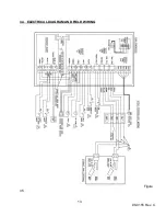
Page 18: ...13 98 0155 Rev C 3 4 ELECTRICAL DIAGRAM AND FIELD WIRING Figure 3 5 ...
Page 19: ...14 98 0155 Rev C Fig Figure 3 6 ...
Page 20: ...15 98 0155 Rev C Figure 3 7 ...
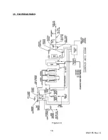
Page 21: ...16 98 0155 Rev C 3 5 FLOW DIAGRAMS Figure 3 8 ...
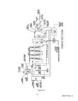
Page 22: ...17 98 0155 Rev C Figure 3 9 ...
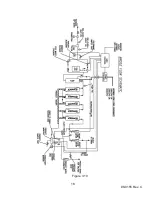
Page 23: ...18 98 0155 Rev C Figure 3 10 ...
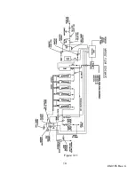
Page 24: ...19 98 0155 Rev C Figure 3 11 ...
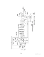
Page 25: ...20 98 0155 Rev C Figure 3 12 ...
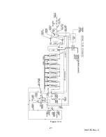
Page 26: ...21 98 0155 Rev C Figure 3 13 ...
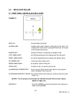
Page 46: ...41 98 0155 Rev C FIGURE 6 3 ...


