34
98-0155 Rev. C
5.3 MEMBRANE FLUSH FEATURE (AUTO FLUSH)
The MRO3Z-MRO8Z sizes are connected to a loop or storage tank only having 1-2 days of
non-use when dialysis procedures are not being carried out. The MEMBRANE FLUSH
FEATURE is the preferred means for minimizing bacterial growth for the MRO3Z-MRO8Z
during periods when dialysis procedures are not being carried out. The MRO3Z-MRO8Z can
be set up to discourage microbiological growth by “flushing” periodically.
The Membrane Flush feature is disabled as a default from the factory for MRO3Z-MRO8Z
models. Refer to the default set points in Section 6.4. If these default settings do not meet
your particular need, then they can be changed. See Section 6.5 on how to change from the
default settings.
FLUSH MODE
RO PUMP
INLET VALVE
DIVERT VALVE
3
(FOR STORAGE TANK APPLICATIONS)
ON
OPEN
ENABLED
4
(FOR LOOP APPLICATIONS)
ON
OPEN
DISABLED
FLUSH MODE #3
assumes that the
MROZ is connected to a storage tank
and, therefore,
will divert the PRODUCT WATER to the drain. This minimizes bacterial growth and directs all
the water to the drain, rather than refill the storage tank.
FLUSH MODE #3
will cause all the
water to be diverted to drain for each MEMBRANE AUTO FLUSH cycle.
On the other hand, when an
MROZ is connected to a Direct Feed Loop
, the PRODUCT
water should be directed into the loop during the MEMBRANE AUTO FLUSH cycle to keep
the water in the loop “fresh”. Setting the
FLUSH MODE for #4
will disable the DIVERT TO
DRAIN feature, and the PRODUCT WATER will be circulated through the loop during each
MEMBRANE AUTO FLUSH cycle. The MEMBRANE AUTO FLUSH will operate while the
MROZ is in the STANDBY mode, while connected to the loop even though no water is being
used for dialysis.
SETPOINT SETTING
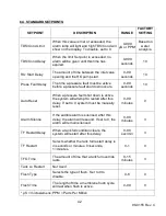
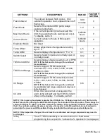
Flush Type
6 (Off hours)
Flush Time
30 to 60 (minutes)
Flush Mode
3 (Inlet valve open, pump on)
Flush Interval
4 to 12 (hours)
The MROZ must be connected to the electric power source, incoming water supply, and drain
at all times for this feature to be operable.
The Flush Time and Flush Interval settings are recommended settings, but may be adjusted
to fit your specific needs. Contact your AmeriWater representative for guidance.
Summary of Contents for MRO3Z
Page 2: ...98 0155 Rev C ...
Page 5: ...98 0155 Rev C ...
Page 13: ...8 98 0155 Rev C MRO7Z and MRO8Z CONFIGURATION SHOWN BELOW Figure 3 2 ...
Page 15: ...10 98 0155 Rev C 3 2 INTERNAL CABINET TOP AND SIDE VIEW Figure 3 3 ...
Page 16: ...11 98 0155 Rev C 3 3 INTERNAL CABINET TOP AND SIDE VIEW CONT Figure 3 4 ...
Page 18: ...13 98 0155 Rev C 3 4 ELECTRICAL DIAGRAM AND FIELD WIRING Figure 3 5 ...
Page 19: ...14 98 0155 Rev C Fig Figure 3 6 ...
Page 20: ...15 98 0155 Rev C Figure 3 7 ...
Page 21: ...16 98 0155 Rev C 3 5 FLOW DIAGRAMS Figure 3 8 ...
Page 22: ...17 98 0155 Rev C Figure 3 9 ...
Page 23: ...18 98 0155 Rev C Figure 3 10 ...
Page 24: ...19 98 0155 Rev C Figure 3 11 ...
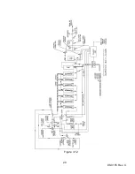
Page 25: ...20 98 0155 Rev C Figure 3 12 ...
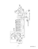
Page 26: ...21 98 0155 Rev C Figure 3 13 ...
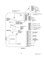
Page 46: ...41 98 0155 Rev C FIGURE 6 3 ...

