54
98-0155 Rev. C
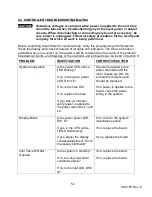
9.2 CONTROLLER TROUBLESHOOTING MATRIX
CAUTION:
Hazardous voltages are present when power is applied to the unit. Care
should be taken when troubleshooting any of the input power or output
circuits. When disconnecting or connecting any board or accessory, be
sure power is unplugged. Follow all safety procedures for the facility and
company for which all work is being performed.
Before contacting AmeriWater for technical help, verify the programming of all Setpoints,
check the display and check the status of all lights and indicators. The more information
available when you contact us, the easier it will be to determine the source of the problem.
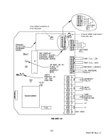
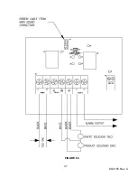
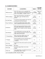
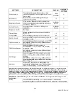
Standard set points, and drawings of the controller and pc boards can be found in Section 6.
PROBLEM
INVESTIGATION
CORRECTIVE ACTION
System Inoperative
Is the yellow CPU active
LED blinking?
If no, is the green power
LED, DS1 Lit?
If no, is the fuse OK?
If no, replace the fuse.
If yes, with a voltmeter,
verify power is applied to
the power terminals L1 and
L2.
If power is applied to the
power terminals and the
other checks are OK, the
pc board is defective and
should be replaced.
If no power is applied to the
board, check the power
wiring to the system.
Display Blank
Is the green power LED,
DS1 lit?
If yes, is the CPU active
LED, DS9 blinking?
If yes, adjust the display
contrast adjustment, R3. Is
the display still blank?
If no, refer to the system
inoperative section.
If no, replace the board.
If yes, replace the board.
Inlet Valve Will Not
Operate
Is the system in standby?
If no, are any shut down
conditions active?
If no, is the inlet LED, DS8
lit?
If no, replace the board.
If no, replace the board.
Summary of Contents for MRO3Z
Page 2: ...98 0155 Rev C ...
Page 5: ...98 0155 Rev C ...
Page 13: ...8 98 0155 Rev C MRO7Z and MRO8Z CONFIGURATION SHOWN BELOW Figure 3 2 ...
Page 15: ...10 98 0155 Rev C 3 2 INTERNAL CABINET TOP AND SIDE VIEW Figure 3 3 ...
Page 16: ...11 98 0155 Rev C 3 3 INTERNAL CABINET TOP AND SIDE VIEW CONT Figure 3 4 ...
Page 18: ...13 98 0155 Rev C 3 4 ELECTRICAL DIAGRAM AND FIELD WIRING Figure 3 5 ...
Page 19: ...14 98 0155 Rev C Fig Figure 3 6 ...
Page 20: ...15 98 0155 Rev C Figure 3 7 ...
Page 21: ...16 98 0155 Rev C 3 5 FLOW DIAGRAMS Figure 3 8 ...
Page 22: ...17 98 0155 Rev C Figure 3 9 ...
Page 23: ...18 98 0155 Rev C Figure 3 10 ...
Page 24: ...19 98 0155 Rev C Figure 3 11 ...
Page 25: ...20 98 0155 Rev C Figure 3 12 ...
Page 26: ...21 98 0155 Rev C Figure 3 13 ...
Page 46: ...41 98 0155 Rev C FIGURE 6 3 ...

