background image

Installation Instructions

Page 29

Pub. No. 41-5016-12

HIGH ALTITUDE DERATE

Input ratings (BTUH) of these furnaces are based on sea level
operation and should not be changed at elevations up to 2,000 ft.

If the installation is 2,000 ft. or above, the furnace input rate
(BTUH) shall be reduced 4% for each 1,000 ft. above sea level.  The
furnace input rate shall be checked by clocking the gas flow rate
(CFH) and multiplying by the heating value obtained from the
local utility supplier for the gas being delivered at the installed
altitude.

Input rate changes can be made by adjusting the manifold pres-
sure (min 3.0 - max 3.7 in. W.C. - Natural Gas) or changing orifices
(orifice change may not always be required). If the desired input
rate cannot be achieved with a change in manifold pressure, then
the orifices must be changed.

LP installations will require an orifice change. See Table 13 for
help in selecting orifices if orifice change is required.

IMPORTANT:
Reinstall the propane orifices to the same depth as the orifices
supplied with the equipment.

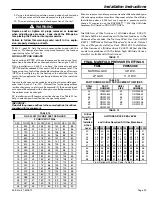
TABLE 10

GAS FLOW IN CUBIC FEET PER HOUR

2 CUBIC FOOT DIAL

SEC. FLOW

SEC. FLOW

SEC. FLOW

SEC. FLOW

8

900

29

248

50

144

82

88

9

800

30

240

51

141

84

86

10

720

31

232

52

138

86

84

11

655

32

225

53

136

88

82

12

600

33

218

54

133

90

80

13

555

34

212

55

131

92

78

14

514

35

206

56

129

94

76

15

480

36

200

57

126

96

75

16

450

37

195

58

124

98

73

17

424

38

189

59

122

100

72

18

400

39

185

60

120

104

69

19

379

40

180

62

116

108

67

20

360

41

176

64

112

112

64

21

343

42

172

66

109

116

62

22

327

43

167

68

106

120

60

23

313

44

164

70

103

124

58

24

300

45

160

72

100

128

56

25

288

46

157

74

97

132

54

26

277

47

153

76

95

136

53

27

267

48

150

78

92

140

51

28

257

49

147

80

90

144

50

TABLE 12

PART NUMBERS FOR REPLACEMENT ORIFICES

DRILL

SIZE

PART

NUMBER

DRILL

SIZE

PART

NUMBER

44
45
46
47
48
49
50

ORF00501

ORF00644
ORF00909
ORF00910
ORF01099
ORF00503
ORF00493

54
55
56
57
58
59

ORF00555
ORF00693
ORF00907
ORF00908
ORF01338
ORF01339

TABLE 13

Orifice

Twist Drill

Size If

Installed

At Sea

Level

ALTITUDE ABOVE SEA LEVEL

and Orifice Required At Other Elevations

2000 3000 4000 5000 6000 7000 8000 9000 10000

42
43
44
45
46
47

42

44
45
46
47
48

43
44
45
47
47
48

43
44
45
47
47
49

43
45
46
47
48
49

44
45
47
48
48
49

44
46
47
48
49
50

45
47
48
49
49
50

46
47
48
49
50

51

47
48
50
50
51
52

54
55
56
57
58

54
55
56
58
59

55
55
56
59
60

55
55
57
59
60

55
56
57
60

61

55
56
57
60
62

55
56
58

61

62

56
56
59
62
63

56
56
59
63
63

56
57
60
63
64

From National Fuel Gas Code - Table F-4

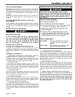
TABLE 11

FINAL MANIFOLD PRESSURE SETTINGS

FUEL

PRESSURE

NATURAL GAS

3.5" W.C.

LP GAS

11.0" W.C.

Installation of this furnace at altitudes above 2,000 ft.
(610m) shall be in accordance with the local codes, or in the
absence of local codes, the 

National Fuel Gas Code, ANSI

Z223.1/ NFPA 54

 or 

National Standard of Canada, Natural

Gas and Propane Installation Code, CSA 149.1

. Installation

of this furnace at altitudes above 2,000 ft. (610m) shall be
made in accordance with the listed high Altitude Conver-
sion Kit available with this furnace.

   9. Using a leak detection solution or soap suds, check for leaks

at the pressure outlet boss and pressure tap test screw.

   10.  Turn on system power and check operation of the unit.

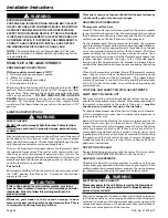
WARNING

!

Replace and/ or tighten all plugs removed or loosened
when adjusting gas pressure.  Leak check the fittings be-
fore placing the Furnace into regular service.

Failure to follow this warning could result in fire, explo-
sion, property damage, or death.

Table 9 – page 24, lists the main burner orifices used with the
furnace.  If a change of orifices is required to correct the furnace
input rating refer to Table 12.

Furnace input rate and temperature rise should be checked again
after changing orifices to confirm the proper rate for the altitude.

Installations above 4,000 feet may require a pressure switch
change. If required, use the BAYHALT*** Kit (High Altitude
Accessory Kit) listed in PRODUCT DATA.

Summary of Contents for CDX1B040A9241A

Page 1: ...yandistoremainwiththisunit Pleasereturntoserviceinformationpackuponcompletionofwork 2011 American Standard Heating Air Conditioning All Rights Reserved Upflow Horizontal and Downflow Horizontal Single Stage Direct Vent Gas Fired Condensing Furnaces Models can ONLY be rotated to LEFT Side for horizontal installation Upflow Horizontal Downflow Horizontal Since the manufacturer has a policy of contin...

Page 2: ...iped by a Licensed Plumber or Gas Fitter in the Commonwealth of Massachusetts WARNING FIRE OR EXPLOSION HAZARD Failure to follow the safety warnings exactly could result in serious injury death or property damage Improper servicing could result in dangerous operation serious injury death or property damage CARBON MONOXIDE POISONING HAZARD Failure to follow the steps outlined below for each applian...

Page 3: ...1 National Installation Code CAN CGA B149 1 The latest code may be obtained from the American Gas Association Laboratories 400 N Capitol St NW Washington D C 20001 1 800 699 9277 or www aga org These furnaces have been classified as CATEGORY IV furnaces in accordance with latest edition of ANSI Z21 47 CAN CGA 2 3 standards Category IV furnaces operate with positive vent static pressureandwithaflue...

Page 4: ...Installation Instructions Pub No 41 5016 12 Page 4 OUTLINE DRAWING FOR CUX1 FURNACES ALL DIMENSIONS ARE IN INCHES ...

Page 5: ...Installation Instructions Page 5 Pub No 41 5016 12 OUTLINE DRAWING FOR CDX1 FURNACES ALL DIMENSIONS ARE IN INCHES ...

Page 6: ...ased coil in the horizontal position See Figure 4 MPORTANT The 2 4TXC cased coil must be placed downstream of the furnace In horizontal installations the apex of the coil may point either toward or away from the furnace See the 2 4TXC coil Installer s Guide for more details The cased coil is secured to the furnace and both the furnace and the cased coil must be properly supported The brackets moun...

Page 7: ...c acid Cements and glues Antistatic fabric softeners for clothes dryers Masonry acid washing materials AIR FOR COMBUSTION AND VENTILATION Adequate flow of combustion and ventilating air must not be obstructedfromreachingthefurnace Airopeningsprovidedinthe furnace casing must be kept free of obstructions which restrict the flow of air Airflow restrictions affect the efficiency and safe operation of...

Page 8: ... the return air ducts under the floor or through theattic Suchdesignpermitstheinstallationofairreturnremote from the living area i e central hall When the furnace is installed so that the supply ducts carry air circulated by the furnace to areas outside the space containing the furnace the return air shall also be handled by a duct s sealed to the furnace and terminating outside the space contain ...

Page 9: ...CHES PROVIDED FOR SIDE RETURN CUTOUT CUT OUT FOR SIDE FILTER FRONT of Furnace FIGURE 10 FILTER RETAINER BRACKETS FOR SIDE AIR RETURN ON UPFLOW FURNACES If side air return is desired it is necessary to move the 2 filter retainer brackets from the bottom of the furnace and reinstall them on the side The following instructions should be used a Remove the front doors b Remove the filter c Carefully pl...

Page 10: ...ch appliance connected to the venting system being placed into operation could result in carbon monoxide poisoning or death The following steps shall be followed for each appliance connected to the venting system being placed into operation while all other appliances connected to the venting system are not in operation 1 Seal any unused openings in the venting system 2 Inspect the venting system f...

Page 11: ... system properly vents when tested as outlined above return door windows exhaust fans fireplace dampers and any other gas burning appliance to their previous conditions of use If improper venting is observed during any of the above tests the remaining common venting system must be corrected Correction of the remaining common vent system should be done by referring to the latest edition of the Nati...

Page 12: ...on monoxide detector with alarm and battery back up may be installed on the next adjacent floor level b In the event that the requirements of this subdivision can not be met at the time of completion of installation the owner shall have a period of thirty 30 days to comply with the above requirements provided however that during said thirty 30 day period a battery operated carbon monoxide detector...

Page 13: ...s must be properly supported throughout the entire length Connection of the vent pipe to the vent collar should also be accomplished using RTV type sealant This type sealant provides a connection which remains flexible and can be separated in the future if service needs require the removal of the vent pipe for service or clearance NOTE To ensure proper operation at the vent lengths indicated the c...

Page 14: ...y be used for horizontal and vertical terminations IPEX 081216 IPEX 081218 and IPEX 081219 may only be used for horizontal vent terminations Equivalent lengths are IPEX 196009 5 feet IPEX 081216 11 feet IPEX 081218 16 feet and IPEX 081219 21 feet DOWNFLOW HORIZONTAL VENTING TABLE TABLE 9 MAXIMUM VENT LENGTH MODEL DIRECT VENT 2 PIPE SYSTEM MAXIMUM TOTAL EQUIVALENT FEET FOR VENT AND INLET AIR PIPES ...

Page 15: ...ny other appliance 6 inches 15 cm for appliances 10 000 Btuh 3 kw 12 inches 30 cm for appliances 10 000 Btuh 3 kw and 100 000 Btuh 30 kw 36 inches 91 cm for appliances 100 000 Btuh 30 kw 6 inches 15 cm for appliances 10 000 Btuh 3 kw 9 inches 23 cm for appliances 10 000 Btuh 3 kw and 50 000 Btuh 15 kw 12 inches 30 cm for appliances 50 000 Btuh 15 kw K Clearance to a mechanical air supply inlet 6 f...

Page 16: ...building or the combustion air inlet to any other appliance 6 inches 15 cm for appliances 10 000 Btuh 3 kw 12 inches 30 cm for appliances 10 000 Btuh 3 kw and 100 000 Btuh 30 kw 36 inches 91 cm for appliances 100 000 Btuh 30 kw 4 feet 1 2 m below or to side of opening 1 foot 300 m above opening K Clearance to a mechanical air supply inlet 6 feet 1 83m 3 feet 91 cm above if within 10 feet 3m horizo...

Page 17: ...hiscanbeavoidedbyusingtherooforchimneyterminal venting option When wall venting is used on any surface that can be affected by this moisture it is recommended that a corrosion resistant shield 24 inches square be used behind the vent terminal This shield can be wood plastic sheet metal etc Also silicone caulk all cracks seams and joints within 3 feet of the vent COMBUSTIBLE MATERIAL WALL A minimum...

Page 18: ... CAP COMBUSTION AIR STRAP FIELD SUPPLIED COMBUSTION AIR VENT ELBOW FIELD SUPPLIED VENT 1 1 2 BAYAIR30AVENTA 3 PIPING 2 2 1 2 or 3 PIPING REDUCING COUPLING FIELD SUPPLIED IF NEEDED SEAL ALL WALL CAVITIES BAYVENT200B x anchor type fasteners suited to the outside or inside wall surfaces NONCOMBUSTIBLE MATERIAL WALL The hole through the wall must be large enough to maintain pitch of vent and properly ...

Page 19: ...inlet pipe must be connected into a condensate drain pump an open or vented drain or it can be connected to the outlet hose of the furnace s condensate trap Outdoor drain ing of the furnace and coil condensate is permissible if allowed by local codes Caution should be taken to prevent drains from freezing or causing slippery conditions that could lead to personal injury Exces sive draining of cond...

Page 20: ...ss steel fitting must be installed with male end towards the furnace All horizontal stainless steel sections must be positioned with the seam on top All long horizontal sections must be supported to prevent sagging All pipe joints must be fastened and sealed to prevent escape of combustion products into the building NOTE Both venting methods shown in Figure 37 39 must also have the combustion air ...

Page 21: ...te leakage to base of masonry chimney m CAUTION Do not run vent through chimney for wood burning or oil furnaces or incinerators or any other gas appliance IMPORTANT The single wall flue pipe joints must be sealed The 90 elbow connection to vertical pipe must be sealed to prevent condensate leakage to base of masonry chimney PVC PLASTIC VENTING ONLY THROUGH UNUSED CHIMNEY SUPPORT THE SINGLE WALL F...

Page 22: ... resizing the remaining vent system HORIZONTAL INSTALLATION UPFLOW HORIZONTAL OR DOWNFLOW HORIZONTAL NOTE In horizontal venting when the factory supplied off set 2X3 reducing coupling is used for 3 vent pipe installation make sure the marking Top is located on the top side of the pipe The straight side must be on bottom for proper condensate drainage This coupling is factory supplied only with the...

Page 23: ...low units this tube may need to be extended using the tubing shipped with the furnace Downflow furnace The furnace is shipped with the left side drainagesetup Tochangetherightsidedrain removethedrain lines from the trap rotate the trap 180 so it exits to the right reconnect the lines and run a 1 2 CPVC pipe from the trap out through the right side knock out Use RTV silicone sealant to connect the ...

Page 24: ...nt condensate pump must be used if a pump is required for a specific drain system IMPORTANT The condensate drain should be installed with provisions to prevent winter freeze up of the condensate drain line Frozen condensate will block drains resulting in furnace shutdown If the drain line cannot be installed in a conditioned space then UL listed heat tape should be applied as required to prevent f...

Page 25: ... the electric circuit The furnace must be electrically grounded in accordance with local codes or in the absence of local codes with the National Electrical Code ANSI NFPA 70 or CSA C22 1 Electrical Code if an external electrical source is utilized The integrated furnace control is polarity sensitive Thehotlegofthe120Vpowersupplymustbeconnected to the black power lead as indicated on the wiring di...

Page 26: ...RAM FOR 1 STAGE FURNACE 1 STAGE HEATING 1 STAGE COOLING USING A 1 STAGE HEATING 1 STAGE COOLING COMFORT CONTROL OUTDOOR SECTION WITHOUT TRANSFORMER COMFORT CONTROL FIELD WIRING DIAGRAMS From Dwg B340433 Rev 2 SEE NOTE 6 B C B C TO 115 V 1 PH 60 HZ POWER SUPPLY PER LOCAL CODES FIELD WIRING DIAGRAM FOR 1 STAGE FURNACE 1 STAGE HEATING USING A 1 STAGE HEATING COMFORT CONTROL NO COOLING COMFORT CONTROL...

Page 27: ...s flow in cfh Table 10 with the time clocked 4 Read the Flow column opposite the number of seconds clocked 5 Use the following factors if necessary For 1 Cu Ft Dial Gas Flow CFH Chart Flow Reading 2 For 1 2 Cu Ft Dial Gas Flow CFH Chart Flow Reading 4 For 5 Cu Ft Dial Gas Flow CFH 10X Chart Flow Reading 4 6 Multiply the final figure by the heating value of the gas obtainedfromtheutilitycompanyandc...

Page 28: ...UAL SHUT OFF MAIN MANUAL SHUT OFF VALVE GROUND UNION JOINT DRIP LEG THE DOWNFLOW VERTICAL MAY BE INSTALLED LEFT OR RIGHT SIDE GAS PIPING FIGURE 33 FIGURE 34 White Rodgers 36G gas valve Outlet Pressure Boss Outlet Pressure Boss On Off ff Swi Switch ch Inlet Pressure let Pressure Boss Boss opt Regul ulator tor Adj Adjust ust White Rodgers 36J gas valve Outlet Pressure Boss Regulator Adjustment Inlet...

Page 29: ...10 ORF01099 ORF00503 ORF00493 54 55 56 57 58 59 ORF00555 ORF00693 ORF00907 ORF00908 ORF01338 ORF01339 TABLE 13 Orifice Twist Drill Size If Installed At Sea Level ALTITUDE ABOVE SEA LEVEL and Orifice Required At Other Elevations 2000 3000 4000 5000 6000 7000 8000 9000 10000 42 43 44 45 46 47 42 44 45 46 47 48 43 44 45 47 47 48 43 44 45 47 47 49 43 45 46 47 48 49 44 45 47 48 48 49 44 46 47 48 49 50 ...

Page 30: ...NG ELECTRICAL SHOCK HAZARD Disconnect power to the unit before removing the blower door Failure to follow this warning could result in property damage personal injury or death This unit is equipped with a blower door switch which cuts power to the blower and gas valve causing shutdown when the door is removed Operation with the door removed or ajar can permit the escape of dangerous fumes All pane...

Page 31: ...D DRAFT BLOWER FAILURE If pressure is not sensed by the pressure switch the contacts will remainopenandnotallowthegasvalvetoopen thereforetheunit willnotstart Iffailureoccursduringarunningcycle thepressure switch contacts will open and the gas valve will close to shut the unit down WARNING The following warning complies with State of California law Proposition 65 This product contains fiberglass w...

Page 32: ...r furnace If additional insulation is added after the furnace is installed the area around the furnace must be inspected to ensure it is free and clear of insulation If this furnace is installed in an attic or other insulated space it must be kept free and clear of all insulating materials as some insulating materials are combustible Furnaces must have air for proper performance There must be a fr...

Page 33: ...out and spraying may generate fiber concentrations requiring additional respiratory protection Use the appropriate NIOSH approved respirator in these situations FIRST AID MEASURES Eye Contact Flush eyes with water to remove dust If symptoms persist seek medical attention Skin Contact Wash affected areas gently with soap and warm water after handling WARNING SAFETY HAZARD BODILY INJURY CAN RESULT F...

Page 34: ...y and set thermostat to desired setting Combustion blower will start and ignition device will start to heat up After approximately 15 seconds main gas valve will open and burners will ignite 8 When thermostat is satisfied main burners will extinguish 9 If main burners fail to ignite lower thermostat setting or disconnect electrical supply wait 5 minutes raise thermostat setting above indicated tem...

Page 35: ...VE WITH MANUAL SHUTOFF MAIN MANUAL SHUTOFF VALVE GROUND UNION JOINT DRIP LEG MAIN MANUAL SHUTOFF VALVE GROUND UNION JOINT DRIP LEG AUTOMATIC GAS VALVE WITH MANUAL SHUTOFF THE DOWNFLOW VERTICAL MAY BE INSTALLED LEFT OR RIGHT SIDE GAS PIPING UPFLOW LEFT HAND GAS PIPING UPFLOW RIGHT HAND GAS PIPING AUTOMATIC GAS VALVE WITH MANUAL SHUTOFF MAIN MANUAL SHUTOFF VALVE GROUND UNION JOINT DRIP LEG AUTOMATIC...

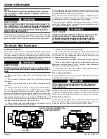
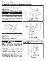
Page 36: ...lacingyourfurnacefilters alwaysuseahighvelocitytype which are the same size as originally supplied Filters are avail able from your dealer Wheredisposablefiltersareused theymustbeahighvelocitytype which are the same size as originally supplied How to remove your filter WARNING ELECTRIC SHOCK HAZARD DISCONNECT POWER TO UNIT BEFORE REMOVING BLOW ER DOOR FAILURE TO FOLLOW THIS WARNING COULD RE SULT I...

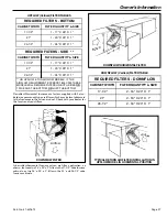
Page 37: ... TABLE REQUIRED FILTERS SIDE CABINET WIDTH FILTER QUANTITY SIZE 17 1 2 1 17 X 25 X 1 21 1 20 X 25 X 1 24 1 2 1 24 X 25 X 1 ON UPFLOW 5 TON AIRFLOW MODELS IF THE AIRFLOW REQUIREMENT EXCEEDS 1800 CFM THESE MODELS WILL REQUIRE FILTERS ON BOTH SIDES OR 1 SIDE AND THE BOTTOM OR JUST THE BOTTOM REQUIRED FILTERS DOWNFLOW CABINET WIDTH FILTER QUANTITY SIZE 17 1 2 2 16 X 20 X 1 21 2 16 X 20 X 1 24 1 2 2 16...

Page 38: ...es and eye protection Wash clothes separately from other clothing rinse washer thoroughly Operations such as sawing blowing tear out and spraying may generate fiber concentrations requiring additional respiratory protection Use the appropriate NIOSH approved respirator in these situations FIRST AID MEASURES Eye Contact Flush eyes with water to remove dust If symptoms persist seek medical attention...

Page 39: ...ease note that it is very fragile and should be handled with care CAUTION DO NOT touch igniter It is extremely hot 4 BURNER Gas burners do not normally require scheduled servicing however accumulation of foreign material may cause a yellowing flame or delayed ignition Either condition indicates that a service call is required For best operation burners must be cleaned annually using brushes and va...

Page 40: ... venting system for proper size and horizontal pitch as required in the National Fuel Gas Code ANSI Z223 1 NFPA 54 or the CAN CGA B149 Installation Codes and these instructions Determine that there is no blockage or restriction leakage corrosion and other deficiencies which could cause an unsafe condition 3 As far as practical close all building doors and windows and all doors between the space in...

Page 41: ...e Ignition Multiport Inshot 3 115 1 60 8 3 15 1 2 H x W x D 41 3 4 x 19 1 2 x 30 1 2 150 140 CUX1B080A9421A Upflow 80 000 74 000 35 65 90 0 DIRECT 10 x 8 1 4 See Fan Performance Table 1 3 1075 115 1 60 Centrifugal Direct 1 1 25 3200 115 1 60 1 35 No High Velocity 1 17x25 1in 2 Round Aluminized Steel Type I 20 4 45 4 56 Redundant Single Stage Hot Surface Ignition Multiport Inshot 4 115 1 60 9 4 15 ...

Page 42: ...le 1 3 1075 115 1 60 Centrifugal Direct 1 1 55 3000 115 1 60 1 0 No High Velocity 2 14x20 1in 2 Round Aluminized Steel Type I 20 3 45 3 56 Redundant Single Stage Hot Surface Ignition Multiport Inshot 3 115 1 60 9 1 15 1 2 H x W x D 41 3 4 x 19 1 2 x 30 1 2 155 145 CDX1B080A9421A Downflow Horizontal 80 000 74 000 40 70 90 0 DIRECT 11 x 8 1 4 See Fan Performance Table 1 2 1075 115 1 60 Centrifugal D...

Page 43: ...ed 2411 2108 1772 1480 2358 2083 1759 1477 2304 2058 1745 1474 2235 2007 1723 1458 2165 1956 1700 1441 2083 1893 1657 1414 2001 1829 1613 1386 1915 1754 1544 1327 1828 1679 1475 1268 CUX1D120A9601A 4 3 2 1 HIGH Black MED HIGH Blue MED LOW Yellow LOW Red 2454 2105 1747 1445 2406 2092 1742 1447 2358 2078 1736 1449 2310 2045 1720 1440 2261 2012 1703 1430 2184 1950 1677 1400 2106 1887 1651 1369 2017 1...

Page 44: ...MODEL Cubic Feet Per Minute CFM 600 700 800 900 1000 1100 1200 1300 1400 1500 1600 1700 1800 1900 2000 2100 2200 2300 2400 CDX1B040A9241A 56 48 42 37 34 CDX1B060A9361A 63 56 51 46 42 39 36 34 CDX1B080A9421A 68 61 56 52 48 45 42 40 CDX1C100A9481A 65 60 56 53 50 47 44 42 40 38 37 35 CDX1D120A9601A 67 63 59 56 53 51 48 46 44 42 WARNING EXPLOSION HAZARD NEVER USE AN OPEN FLAME TO DETECT GAS LEAKS EXPL...

Page 45: ...asburnersdonotnormallyrequirescheduled servicing however accumulation of foreign material may cause a yellowing flame or delayed ignition Either condition indicates that a service call is required For best operation burners should be cleaned annually by a qualified servicer Turn off gas and electric power supply To clean burners remove the top burner bracket Lift burners from orifices NOTE Be care...

Page 46: ...ashes System Lockout Retries or Recycles exceeded 3 Flashes Draft Pressure Error Possible problems a Venting problem b Pressure switch problem c Inducer problem 4 Flashes Open Temperature Limit Circuit 5 Flashes Flame sensed when no flame should be present 6 Flashes 115 volt AC power reversed poor grounding or system voltage too low 7 Flashes Gas valve circuit error 8 Flashes Low flame sense signa...

Page 47: ...Service Instructions Page 47 Pub No 41 5016 12 UNIT WIRING DIAGRAM From Dwg D342775 Rev 1 continued on next page ...

Page 48: ...Service Instructions Pub No 41 5016 12 Page 48 SCHEMATIC DIAGRAM From Dwg D342775 Rev 1 ...

Page 49: ...Service Instructions Page 49 Pub No 41 5016 12 UNIT WIRING DIAGRAM From Dwg D342798 Rev 0 continued on next page ...

Page 50: ...Service Instructions Pub No 41 5016 12 Page 50 SCHEMATIC DIAGRAM From Dwg D342798 Rev 0 ...

Page 51: ...rd the purchase price of a comparable heating unit Any other costs such as local transportation related service labor diagnosis calls refrigerant and related items are not included This limited warranty does not apply if the gas furnace was purchased direct i e from internet websites or auctions on an uninstalled basis Additionally this limited warranty will not apply unless the gas furnace is 1 i...

Page 52: ...lity shall attach to Warrantor until products have been paid for and then liability shall be limited solely to the purchase price of the equipment under warranty shown to be defective This limited warranty does not apply if the gas furnace was purchased direct i e from internet websites or auctions on an uninstalled basis Additionally this limited warranty will not apply unless the gas furnace is ...

Page 53: ..._________________________________________________________________ Indoor Coil Serial Number______________________________________________________________________________ Indoor Coil Model Number______________________________________________________________________________ Date of Installation_____________________________________________________________________________________ Dealer_______________...

Page 54: ...ndard Heating Air Conditioning 6200 Troup Hwy Tyler TX 75707 Pub No 41 5016 12 As an ENERGY STAR Partner American Standard Inc has determined that this product meets the ENERGY STAR guidelines for energy efficiency ...

Reviews: