18
American-Lincoln
SC7750 IC
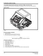
FOOT BRAKE (See Figure 16)
The foot brake pedal is located on the floor of the operator’s
compartment to the left of the directional control pedal. To
stop, use the front wheel brakes, by putting pressure on the
brake pedal.
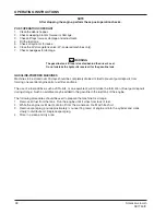
PARKING BRAKE (See Figure 17)
The parking brake lever is located on the operator’s com-
partment left side panel near the floor. When
engaged, the parking brake “locks” the foot pedal in the
down position.
To engage the parking brake, place lever in the upright
position.
To disengage the parking brake, move the lever forward.
To adjust the parking brake “grab”, turn the knob on the top
of the lever. To increase the “grab”, turn the knob in a
clockwise direction.
To decrease the “grab”, turn the knob in a counterclockwise
direction.
FWD/REV FOOT PEDAL (See Figure 18)
The foot pedal is located on the floor of the operator’s
compartment to the right of the brake pedal. The foot
pedal provides control of direction/speed. The pedal height
is adjustable to provide for operator comfort.
To adjust the foot pedal height for operator comfort;
1.
Remove the hairpin cotter from the adjustment pin.
2.
Remove adjustment pin from the foot pedal assembly.
3.
Align the holes in the lower bracket with one of the four
adjustment holes on the foot pedal to set the foot pedal
height.
4.
With the holes aligned at the desired height, insert
the adjustment pin.
5. Re-install the hairpin cotter.
TO GO FORWARD:
Place pressure on the upper portion
of the pedal. Speed increases when additional pressure is
placed on the pedal.
TO GO BACKWARD:
Place pressure on the lower portion
of the pedal. Speed decreases when additional pressure is
placed on the pedal.
TO STOP:
Allow the pedal to return to the centered posi-
tion.
To increase braking action while moving in reverse gently
put pressure on the upper portion of the pedal.
ADJUSTM
EN
T
P
IN
ADJUSTM
EN
T
H
OL
E
S
H
A
I
RP
IN
COTT
E
R
R
E
V
E
RS
E
NE
UTRAL
F
ORWARD
C1789/9810
C
I
RCUT BREAKERS
PARKING
BRAKE
C
I
RCUT BREAKERS
Amer
i
can
-
L
i
nco
l
n
0
1/2
4
/
4
F
U
E
L
F
OOT P
E
DAL
C163
4
C1634-1
FIGURE 16
C1635
FIGURE 17
C1789
FIGURE 18
OPERATION OF CONTROLS AND GAUGES


