American-Lincoln
13
SC7750 IC
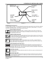
FILTER SHAKER SWITCH (See Figure 6)
The filter shaker switch is located on the instrument panel
below the ignition switch. This is a momentary switch that
will activate the filter shaker motors for 20 to 30 seconds to
clear the dust control filter. The Impeller fan will stop when
the filter shaker has been activated. The filter shaker will
only operate with the hopper in the “DOWN” position.
Use the filter shaker to clear the filter when the dust control
light comes on (warning bank) and just before dumping the
hopper.
GLOW PLUG SWITCH (Diesel) (See Figure 6)
Under no circumstances should any other unauthorized
starting aids be used at the same time as Glow Plugs.
The Glow Plug Switch is located to the right of the steering
column on the front face of the instrument console. Use the
following procedure to operate.
1.
Before operating the starter motor, press the “GLOW
PLUG” switch for 20 to 30 seconds.
2.
With the “GLOW PLUG” switch still depressed, engage
the starter motor until the engine starts.
3.
Continue to press the “GLOW PLUG” switch for a few
seconds after the engine has started until even running
has been obtained.
4.
If the engine does not start, disengage the starter motor,
but keepthe “GLOW PLUG” switch depressed for a
further 10 to15 seconds, when a further attempt should
be made to start the engine, keeping the Glow Plugs
energized while starting and for a few seconds after the
engine has fired until it is running smoothly.
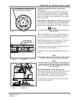
SEAT COMPARTMENT PROP LATCH (See Figure 7)
The seat compartment latch is located under the seat
compartment cover and is used to hold the cover open.
To hold the seat compartment cover open, lift the cover and
rotate the latch.
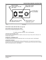
HOPPER SAFETY LOCK ARM (See Figure 8)
The hopper safety arm is located near the right front wheel
well. The safety arm will prevent the hopper from dropping
unexpectedly during service/maintenance.
TO ENGAGE THE SAFETY ARM:
1.
Empty hopper
2.
Set the parking brake.
3.
Raise the hopper.
4.
Lift safety arm to engage the slot on the hopper frame.
5.
When work has been completed, replace the safey arm
to the stowed position.
WARNING
When the hopper is raised, the safety arm must be engaged
before ANY work is done under the hopper.
OPERATION OF CONTROLS AND GAUGES
HOPP
ER
SA
F
ET
Y
AR
M
T
O
E
NG
A
G
E
MOD
E
L
N
O
.
S
E
R
I
AL
N
O
.
WAR
NIN
G
C1700
3
C1640-2
FIGURE 6
C1699a
FIGURE 7
C1700
FIGURE 8
FILTER
SHAKER
SWITCH
GLOW
PLUG
SWITCH


