Amcrest IP4M-1048EB User Manual Download Page 30


30        


Below is an explanation for each of the fields on the Audio menu:  
  

• 

Enable

: This checkbox allows the user to enable audio recording.          

• 

Encode Mode

: This dropdown box allows the user to select what audio format the audio should be recorded in.          

• 

Sampling Frequency

: This dropdown box allows the user to select a sampling frequency for the audio. The options 

are 8k and 16k. 16k audio sampling allows for higher sound quality.          

• 

Audio in Device

: This field allows the user to select what source to get audio from. 

The default is the camera’s 

built-in mic. Alternatively, the line in mic can be selected.          

• 

Noise Filter

: This dropdown box allows the user to enable or disable the audio noise filter function. This function 

provides cleaner audio quality when enabled.          

• 

Microphone Volume

: This slider allows the user to select the microphone volume. The value ranges from 0 to 100. 

The default value is 50.    
       
To reset to default settings, click the 

Reset Defaults

 button. To refresh the page, click the 

Refresh

 button. To save 

the settings, click the 

Save

 button.       


Network         

This menu section allows the user to change network settings for the camera.    
      

TCP/IP         

The TCP/IP menu item has two tabs: TCP/IP and P2P.         
 

TCP/IP         

TCP/IP stands for Transmission Control Protocol/Internet Protocol and it is the language/protocol that allows 
communication between internet connected devices, whether on a local network, or a on the Internet at large. 
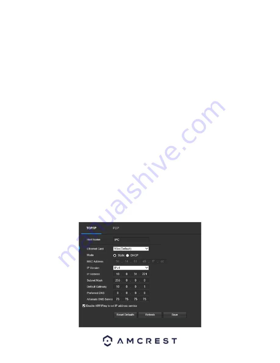
This screen allows for TCP/IP settings to be modified for the camera to establish a connection to the network. 
Below is a screenshot of the TCP/IP settings tab:     


Summary of Contents for IP4M-1048EB

Page 1: ...Amcrest IP4M 1048EW IP4M 1048EB 4MP POE AI Turret Camera User Manual Version 1 0 0 Revised December 19th 2019...

Page 2: ...efault Username and Password 8 How to Setup the Camera 8 App Setup 9 Desktop Access Setup 14 Operation and Interface 16 Live 16 Playback 17 Setup 18 Camera 19 Event 36 Storage 72 Destination 75 System...

Page 3: ...e default password for your camera Always ensure that your password is at least 810 characters long and contains a combination of lowercase characters uppercase characters as well as numbers Important...

Page 4: ...s features It s easy to use and can be viewed on a computer via the built in web user interface or on your smartphone using the Amcrest View Pro app This camera adopts a high quality design to achieve...

Page 5: ...e below shows the structure of the camera The images below show the dimensions for the camera The measurements are in millimeters mm To access the reset button and to adjust the camera angle use a Tor...

Page 6: ...be able to configure the device to your network For more information Installation Guide To install the camera on a ceiling or wall please reference the below diagram as well as the steps Note Prior to...

Page 7: ...era from bottom installation bracket Side Wiring Installation 1 Run the wiring of the camera through the side wire exit groove on the side of the installation bracket and pull firmly and lay the wire...

Page 8: ...up and access your camera through the following methods Local PC Web User Interface Web UI Amcrest Surveillance Pro etc Amcrest View Pro app Amcrest Surveillance Pro Amcrest Cloud Default Username and...

Page 9: ...to use AmcrestView com App Setup Amcrest cameras can be used on your mobile device using the following apps Amcrest Cloud Amcrest View Pro Both apps are free and available in the App Store and Google...

Page 10: ...ra 4 Give your camera a name Ex Garage Living Room Kitchen etc and tap Next to continue 5 Scan the QR code on the back side bottom of the camera or manually enter the camera s serial number into the E...

Page 11: ...our camera When all settings have been confirmed tap Finish For more information about the Amcrest Cloud app and its features visit amcrest com support Amcrest View Pro Setup To add your PoE camera to...

Page 12: ...e of the screen to begin adding your PoE device 3 Tap on Add Device to add a new device to your app 4 Tap on PoE Camera 5 Next select a connection type Since we will be setting up a basic P2P connecti...

Page 13: ...efault username and will be admin Tap Start Live View to continue Note You can tap on the icon to verify the password Note Android users tap on Scan QR Code to access the QR code reader 8 The app will...

Page 14: ...nformation below To access your camera from your computer you will need to first locate the camera s IP address To locate the camera s IP address is it highly recommended to download our free Amcrest...

Page 15: ...y the password for your device To modify the password enter the new password you would like to use in the New Password field and confirm The password used should be between 8 and 32 characters long wi...

Page 16: ...view feed from the camera Section 4 This section allows the user to access setup options alarm and logout the interface Section 5 This section allows the user to perform different camera functions whi...

Page 17: ...screen mode Double click the mouse or click the ESC button to exit full screen mode Width Height Ratio This button allows the user to change the width height ratio for the live feed The options are Or...

Page 18: ...ed and downloaded using the Save icon Section 5 This panel allows the user to specify what type of video they would like to playback and it also allows the user to select where to start playback from...

Page 19: ...menu that allows the user to change specific settings for the camera 3 Menu Tab These tabs open menu options for certain menu items Camera This menu section allows the user to change different camera...

Page 20: ...ion may over expose The recommended value ranges from 40 to 60 Saturation This slider is used to adjust playback and recorded video window saturation The value ranges from 0 to 100 The default value i...

Page 21: ...thout sacrificing exposure timing Shutter Priority This setting will maximize the fastest shutter speed and will sacrifice the gain in return Manual This setting lets you select your shutter speed and...

Page 22: ...ight sources like headlights or spotlights To reset to default settings click the Reset Defaults button To refresh the screen click on Refresh To save the settings click the Save button WB This dropdo...

Page 23: ...nt Below is a screenshot of this menu Profile This dropdown box allows the user to select which profile to modify The 3 options are Day Night and Normal Mode This dropdown box allows the user to selec...

Page 24: ...tings click the Save button IR Light This menu allows the user to select whether the IR lights for night vision are on or off for the selected profile Below is a screenshot of this menu Profile This d...

Page 25: ...utton To refresh the screen click on Refresh To save the settings click the Save button Profile Management Below is a screenshot that shows the Profile Management tab in the Configuration menu item Be...

Page 26: ...user to set the resolution The system supports various resolutions and they can be selected from this dropdown list Frame Rate FPS This dropdown box allows the user to select a frame rate Frame rate s...

Page 27: ...he user to select a snapshot mode There are two snapshot modes General Snapshots are taken as scheduled Event Snapshots occur when a motion detection alarm or tampering alarm is triggered Image Size T...

Page 28: ...r Channel Title the radio button enables or disables the feature The Input Channel Title field allows the channel title to be modified For Time the radio button enables or disables the feature Clickin...

Page 29: ...erent destination folder The Playback Download field allows the user to select where to save playback video downloads to Click the Browse button to select a different destination folder The Video Clip...

Page 30: ...r function This function provides cleaner audio quality when enabled Microphone Volume This slider allows the user to select the microphone volume The value ranges from 0 to 100 The default value is 5...

Page 31: ...t Mask and Gateway becomes prohibited MAC Address This field shows the camera s MAC address which is unique to this device This number is read only and is used to access a local area network LAN IP Ve...

Page 32: ...ion tab is where users can configure port connections Below is a screenshot of the Port settings tab Below is an explanation of the fields on the Connection settings tab Max Connections This field all...

Page 33: ...NO IP DDNS CN99 DDNS and Dyndns DDNS Based on which service is selected different options may show on this screen For purposes of this guide AmcrestDDNS will be used AmcrestDDNS is a free DDNS servic...

Page 34: ...n To save the settings click the Save button SMTP Email This screen allows for the configuring of email settings to permit the camera to send emails when an alarm is triggered Below is a screenshot of...

Page 35: ...ut an email to test the connection is OK or not Prior to the email test please save the email setup information To reset to default settings click the Reset Defaults button To refresh the page click t...

Page 36: ...ceeded o The seventh column allows the user to open a dialog box and edit the service s information To reset to default settings click the Reset Defaults button To refresh the page click the Refresh b...

Page 37: ...b allows the user to modify motion detection settings Below is a screenshot of the Motion Detect tab Below is an explanation of the fields on the Motion Detect tab Enable This checkbox enables motion...

Page 38: ...fter 10 seconds if system detects another alarm signal it can generate a new alarm since the anti dither time has expired Detection Area Clicking this button opens a pop up screen that can be used to...

Page 39: ...ed Alarm Delay This field specifies in seconds how long the delay between alarm activation and Relay alarm activation should be Send Email This checkbox allows the user to enable the camera to send an...

Page 40: ...alarm port on the back of the camera when a video tamper alarm is triggered Alarm Delay This field specifies in seconds how long the delay between alarm activation and Relay alarm activation should be...

Page 41: ...ower the sensitivity the more audio variance is required to trigger an alarm Enable Intensity Change This checkbox enables the user to adjust sensitivity and threshold settings for audio detection o S...

Page 42: ...0 seconds if system detects another alarm signal it can generate a new alarm since the anti dither time has expired Record This checkbox allows the user to enable the camera to record video when an au...

Page 43: ...IVS IVS stands for stands for intelligent video system analytics and is the basis for all the AI rules associated with your camera The IVS menu allows the user to customize and set IVS rules which al...

Page 44: ...human or car is detected by the camera Both effective object checkboxes can be activated at the same time Human This checkbox allows the camera to be triggered only when a human figure is detected Mo...

Page 45: ...rule 2 Click on Setup to set a schedule set your periods if any and click Save to continue 3 In the Direction menu choose which direction the object will be going for the tripwire to be triggered 4 An...

Page 46: ...be triggered A Schedule must be set for IVS rules to function Action These checkboxes allow the user to choose a parameter filter that will activate a trigger if an object were to cross or appear in t...

Page 47: ...button To save the settings click the Save button Setting an Intrusion Area 1 Select Intrusion from the Rule Type menu Set a name for the rule by double clicking the mouse over the Name of the rule 2...

Page 48: ...esh the page click the Refresh button To save the settings click the Save button Abandoned Object Abandoned Object allows the camera to trigger an event if an object is placed in a set area for a spec...

Page 49: ...which an event will be triggered Draw Target Allows the user to set a target area on the live monitor screen An IVS event will not occur outside the target box Clear Clears the modified target area to...

Page 50: ...resh the page click the Refresh button To save the settings click the Save button Fast Moving Fast Moving allows the camera to trigger an event if an object such as a human or vehicle quickly moves in...

Page 51: ...This checkbox allows the user to enable the camera to record video when an IVS event is triggered Record Delay This field specifies in seconds how long the delay between IVS events should be The defa...

Page 52: ...cord checkbox to record the event 6 Check the Send Email and Snapshot checkboxes if you would like a snapshot of the event emailed to you A valid Email address must be established in the camera prior...

Page 53: ...is checkbox allows the user to enable the camera to send an email when an IVS event is triggered Snapshot This checkbox allows a snapshot of the IVS event to be sent via Email when triggered Draw Rule...

Page 54: ...Email address must be established in the camera prior to enabling this setting 6 Click the Draw Rule option and right click on the live monitoring screen Use the mouse to draw your initial line Once t...

Page 55: ...ered Record Delay This field specifies in seconds how long the delay between IVS events should be The default is 10 seconds however this can be modified between 10 300 seconds Send Email This checkbox...

Page 56: ...as follows 11 Sensitivity Value x 3 of people required to trigger an event Sensitivity Value 1 2 3 4 5 6 7 8 9 10 11 of People 30 27 24 21 18 15 12 9 6 3 1 4 Enable the Record checkbox to record the...

Page 57: ...ord Delay This field specifies in seconds how long the delay between IVS events should be The default is 10 seconds however this can be modified between 10 300 seconds Send Email This checkbox allows...

Page 58: ...d the event 5 Set the number of seconds the event will be delayed in between triggers It is recommended to leave this as default 6 Enable the Send Email and Snapshot checkboxes if you would like a sna...

Page 59: ...event is triggered Record Delay This field specifies in seconds how long the delay between IVS events should be The default is 10 seconds however this can be modified between 10 300 seconds Send Email...

Page 60: ...d like a snapshot of the event emailed to you A valid Email address must be established in the camera prior to enabling this setting 6 Click the Draw Rule option and right click on the live monitoring...

Page 61: ...ual length of the ruler on the live monitoring screen in meters Add Rulers This option allows the user to add and adjust a ruler on the live monitoring screen Rulers are used to adjust calibration for...

Page 62: ...orizontal ruler radio button and click Add Rulers Draw a horizontal line in the detection area Only one horizontal line can be used in the detection area Left click on the live monitoring screen to se...

Page 63: ...ers exits the set line A B represents if a person enters or exits from the right B A represents of a person enters or exits from the left Enter No The amount of people it takes to trigger a person ent...

Page 64: ...e can be applied Click Save 4 Use the Name option to provide a custom name for your detection line The detection line can be set to default NumberStat1 if necessary 5 Use the Direction dropdown menu t...

Page 65: ...amount of people detected by the camera Below is a screenshot of the Report menu Below is a description of the options in the Report menu Report Type This dropdown menu allows the user to choose whic...

Page 66: ...nerated which will display the number of people who enter or exit a certain area based on a daily monthly or yearly report Below is an example of a generated bar chart The date and time range will be...

Page 67: ...ne represents the amount of exits in the chart and the red line represents the amount of people who entered Heat Map The Heat Map function provides a general reporting of crowd density statistics base...

Page 68: ...Used to search and generate the report Export Allows the user to export an image of the people counting report to their computer Using Heat Map The Heat Map function can be used in conjunction with I...

Page 69: ...settings click the Save button Abnormality This menu allows the user to adjust abnormality event settings This menu has 5 tabs SD Card Network and Illegal Access Voltage Detection Security Exception S...

Page 70: ...b allows the user to set the camera s response to a Network related abnormality Below is a screenshot of the Network tab screen Below is an explanation of the fields on the Network settings tab Event...

Page 71: ...ut This checkbox allows the user to enable the camera to trigger an alarm when illegal access is detected Alarm Delay This field specifies in seconds how long the delay between alarm activation and re...

Page 72: ...y the camera Below is a screenshot of the Security Exception menu Enable This checkbox enables the security exception abnormality trigger for your camera Send Email An email will be sent once the came...

Page 73: ...res only footage when an alarm is activated Alarm recording is represented by the color red Video Recording Schedule To specify a video recording range first select the type of recording desired then...

Page 74: ...s snapshots when an alarm is activated Alarm recording is represented by the color red Snapshot Recording Schedule To specify a snapshot range first select the type of snapshot desired then click and...

Page 75: ...esignated it can be customized to stop recording or snapshots for that day by using the Record and Snapshot checkboxes To refresh the page click the Refresh button To save the settings click the Save...

Page 76: ...on the SD Card settings tab Device Name This column designates the name of the SD card that is currently in the camera Status This column designates the status of the SD card Attribute This column de...

Page 77: ...to the FTP server Password This field allows the user to input the password used to login to the FTP server Remote Directory This field allows the user to specify a remote directory on the FTP to send...

Page 78: ...is comprised of Pre event Record This field allows the user to specify how many seconds before an event should be recorded Disk Full This dropdown box allows the user to designate what the camera shou...

Page 79: ...s field allows the user to change the device s name Language This dropdown box allows the user to change the language used in the camera Video Standard This dropdown box allows the user to select eith...

Page 80: ...er Port This field allows the user to enter in the port number for the NTP server Update Period This field allows the user to enter in the update period time This number designates how frequently the...

Page 81: ...of the Default screen Below is an explanation of the items listed in this field Default Settings Only the IP address user management and other settings can be recovered after reset Factory Default Com...

Page 82: ...save the settings click the Save button Upgrade This menu allows the user to upgrade the camera s firmware Below is a screenshot of the Upgrade screen To upgrade the firmware for your camera follow t...

Page 83: ...n On this screen software version web interface version and ONVIF version are displayed Also the S N Token ID is displayed here Log This screen is where the camera s activity log is kept Below is a sc...

Page 84: ...remote device 1 65534 Device Number The number of the device in the network segment To reset to default settings click the Reset Defaults button To refresh the page click the Refresh button To save th...

Page 85: ...rotocol should be enabled Please refer to your router manufacturer s documentation to learn how to enable uPnP on your router Below is a step by step walkthrough that details how to setup Amcrest came...

Page 86: ...low to ensure the plugin can run successfully 17 Enter in login details into the username and password fields and click login If the process above is not working please contact Amcrest Support via one...

Page 87: ...DNS domain name address from step 21 enter in a colon then type the HTTP port number from step 10 on to the end For example if the DDNS domain name is http abc123456789 AmcrestDDNS com and your HTTP P...

Page 88: ...count You will be required to activate your account by e mail double check your spam folder 3 Once activated download and install the plugin for your web browser The installation of the plugin will re...

Page 89: ...resolve the issue Log into your camera s web user interface via a laptop or PC Navigate to Setup System General Click on the Date Time tab Click on PC Sync to sync the date and time Click Save to sav...

Page 90: ...arm input signal is not correctly configured There are two loops connected to one alarm device 11 Downloaded files cannot be played back Below are a few possible reasons why this may be occurring The...

Page 91: ...a network protocol for encapsulating Point to Point Protocol data packets inside Ethernet frames QR Code Quick Response code is a type of digital barcode that enables devices to share complex data st...

Page 92: ...encouraged to try to correct the interference by one or more of the following measures Reorient or relocate the receiving antenna Increase the separation between the equipment and receiver Connect th...

Page 93: ...oncentration of the hazardous substance of at least one of all homogeneous materials in the parts is above the relevant threshold of the SJ T11363 2006 standard During the environmental friendly use p...

Page 94: ...h kind of substances or elements please return to the corresponding local authorities to process according to your local government statutes Note To view setup videos for many of the steps outlined in...

Reviews: