Operator’s Manual
AMAZONE
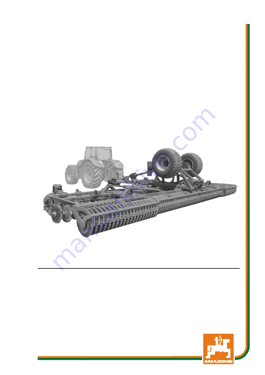
Catros 12003-2TS
Compact Disk Harrow
MG5598 BAG0110.10 10.19 Printed in Germany
Please read, understand and
follow this operator’s manual
before operation.
Keep it in a safe place for
future use.
en-US
Page 1: ...Manual AMAZONE Catros 12003 2TS Compact Disk Harrow MG5598 BAG0110 10 10 19 Printed in Germany Please read understand and follow this operator s manual before operation Keep it in a safe place for future use en US ...
Page 2: ...ly harm himself but also make the mistake of blaming the implement for possible failures instead of himself In order to ensure success one should enter the mind of a thing make himself familiar with every part of the implement and get accustomed with how it is handled Only in this way could one be satisfied both with the implement and with himself This is the goal and purpose of this operator s ma...
Page 3: ...2 Hasbergen Germany Phone Fax E mail 49 5405 501 0 49 5405 501 234 amazone amazone de Spare part orders Spare part lists are freely accessible in the spare parts portal www amazone de Please send spare parts orders to your AMAZONE dealer Operator s manual information Document number MG5598 Compilation date 10 19 Copyright AMAZONEN WERKE H DREYER GmbH Co KG 2019 All rights reserved The reprinting o...
Page 4: ...nual will you be able to benefit from the full scope of your newly purchased implement and will be able to operate this implement in a safe manner Please ensure that all implement operators have read this operator s manual before they operate this implement Should you have problems or questions please consult this opera tor s manual or give your Amazone dealer a call Regular maintenance and timely...
Page 5: ...1 General safety and accident prevention 23 2 16 2 Hydraulic system 26 2 16 3 Electrical system 27 2 16 4 Attached implements 27 2 16 5 Brake system 28 2 16 6 Tires 29 2 16 7 Cleaning maintenance and repairs 29 3 Loading and Unloading 30 4 Product Description 31 4 1 Overview of implement assembly 31 4 2 Safety and protection equipment 33 4 3 Power supply cables between tractor and implement 33 4 4...
Page 6: ...nintentional start up and rolling 68 7 Connecting and disconnecting the implement 69 7 1 Coupling the lower link hitch 72 7 2 Coupling the towing eye ball bracket 73 8 Adjustments 75 8 1 Working depth 75 8 1 1 Mechanical working depth adjustment 76 8 1 2 Hydraulic working depth adjustment 76 9 Transportation 77 9 1 Conversion from operational to transport position 79 10 Use of the Implement 81 10 ...
Page 7: ...ines labeling 104 12 10 2 Maintenance intervals 104 12 10 3 Inspection criteria for hydraulic hose lines 104 12 10 4 Installation and removal of hydraulic hose lines 105 12 11 Hydraulics diagram 106 12 12 Bolt tightening torques 110 13 Brief instructions 111 Catros BAG0110 10 10 19 7 ...
Page 8: ...ewed in the direction of travel 1 3 Diagrams Instructions for action and reactions Tasks to be carried out by the operator are presented as numbered instructions Always follow the order of the instructions The reactions to the instructions are given by an arrow Example 1 Instruction for action 1 Reaction of the implement to instruction for action 1 2 Instruction for action 2 Lists Lists without a ...
Page 9: ...ning labels If you still have questions please contact your Amazone dealer Obligations of the operator Before starting work all persons working with on the implement are obligated to comply with the basic workplace safety instructions and accident prevention regulations read and understand the section General safety information of this operator s manual read the section Warning labels and other sa...
Page 10: ...manager at the latest on the completion of the purchase contract Guarantee and liability claims for damage to people or goods will be excluded if they can be traced back to one or more of the following causes improper use of the implement improper installation commissioning operation and mainte nance of the implement operation of the implement with defective safety equipment and or improperly atta...
Page 11: ...ical injury WARNING indicates a medium risk which could result in death or serious physical injury if not avoided Failure to follow these instructions may result in death or seri ous physical injury CAUTION indicates a low risk which could result in minor or moderate physical injury and or damage to property if not avoided IMPORTANT indicates a specific obligation or requirement for proper imple m...
Page 12: ...ive equipment Before each operation of the implement all the safety and protective equipment must be properly attached and fully functional Check all safety and protective equipment regularly Faulty safety equipment Faulty or disassembled safety and or protective equipment can lead to dangerous situations 2 5 Additional safety measures As well as all of the safety information in this operator s ma...
Page 13: ...ns are those who have been instructed in their assigned tasks and in the possible risks in the case of improper behavior have been trained if necessary and have been in formed about the necessary protective equipment and measures 3 People with specialist technical training shall be considered as a specialist Due to their specialist training and their knowledge of the appropriate regulations they c...
Page 14: ... from unintentional start up Carefully fix and secure larger subassemblies to lifting gear when carrying out replacement work Check that all bolt connections are tight After completing mainte nance work check the function of safety and protection equipment 2 10 Constructive modifications You may not make changes additions or modifications to the implement without receiving authorization from AMAZO...
Page 15: ...e that they have been designed and manufactured in such a way as to meet the requirements placed on them AMAZONEN WERKE accepts no liability for the damage arising from the use of unapproved spare parts wear parts or auxiliary materials 2 11 Cleaning and disposal Handle and dispose of any materials used carefully especially when carrying out work on lubrication systems and equipment and cleaning w...
Page 16: ...s 2 13 Warning labels and other safety markings on the implement 2 13 1 Positioning of warning labels and other labels The following diagrams show the arrangement of the warning labels on the implement 16 Catros BAG0110 10 10 19 ...
Page 17: ...t symbol along with a signal word which indi cates the level of danger Field 3 explains the type of hazard as well as how to avoid it Field 4 is where the order number is located Warning pictorial explanation In the following pages the individual warning labels will be explained in more detail The column on the left Order number and explanation provides an explanation of the warning pictorial on t...
Page 18: ...NG PINCH HAZARD Secure tractor and machine and wait until all parts have stopped before reaching into danger area Make sure nobody is in the danger area or near any moving parts MO006 WARNING CUTTING HAZARD Secure tractor and machine until all parts have stopped moving before reaching into danger area Keep others clear of danger area and near any moving parts MD007 WARNING HIGH PRESSURE HYDRAULIC ...
Page 19: ...hocks to secure machine MO010 DANGER ELECTROCUTION HAZARD Never touch any power line with the ma chine Always keep a safe distance from all power lines during transport and folding or unfold ing the machine s components Note that the voltage can also flash over when the distance is too small MO011 WARNING LIFTING POINT This symbol indicates lifting points for fastening slings when loading the mach...
Page 20: ...e checked adjusted and repaired by a qualified spe cialist workshop only MO016 WARNING Be sure to secure the tractor and the ma chine before working on the machine MO017 WARNING Only attach the lifting equipment at the marked positions MO020 WARNING FALLING HAZARD To prevent serious injury or death Do not climb on the finishing roller wheels or finishing roller support Keep others away from the fi...
Page 21: ...General Safety Instructions MD114 This symbol indicates a lubrication point Catros BAG0110 10 10 19 21 ...
Page 22: ...reas failure of important implement functions failure of required methods of maintenance and repair danger to people through mechanical and chemical impacts risk to environment through leakage of hydraulic fluid 2 15 Safety conscious operation In addition to the safety information in this operator s manual the national general workplace safety and accident prevention regulations are binding Comply...
Page 23: ...ions the driving characteristics of the tractor and the connected implement Connecting and disconnecting the implement Only connect and transport the implement with tractors suitable for the task When connecting the implement to the tractor three point hydraulic system the attachment categories of the tractor and the implement must be the same Connect the implement to the required equipment in acc...
Page 24: ... ensure that you understand all the equipment and set up elements of the implement and their functions There is no time for this when the implement is in operation Do not wear loose fitted clothing Loose clothing increases the risk of being caught by drive shafts and other sharp extruding objects on the implement Only start up the implement when all the safety equipment has been attached and is in...
Page 25: ...ehicle combination tractor plus connected implement Check the brakes before driving on public roads When turning corners with the implement connected take the gross and balance weight of the implement into account Before transport ensure sufficient side locking of the tractor lower links when the implement is fixed to the three point hydraulic system or lower links of the tractor Before transport ...
Page 26: ...ave the hydraulic hose line checked at least once a year by a specialist for proper functioning Replace the hydraulic hose line if it is damaged or worn Only use AMAZONE original hydraulic hose lines The hydraulic hose lines should not be used for longer than six years including any storage time of maximum two years Even with proper storage and approved use hoses and hose connections are subject t...
Page 27: ...onents on the implement and or a connection to the onboard power supply the user must check whether the installation might cause faults on the vehicle electronics or other components ο Ensure that the retrofitted electrical and electronic components comply with the EMC directive 2004 108 EEC in the appropriate version and carry the CE label 2 16 4 Attached implements Comply with the approved combi...
Page 28: ... on the hose connectors of the supply and brake lines Only transport the the connected implement when the pressure gauge on the tractor shows 72 5 psi 5 0 bar Drain the air tank every day Before moving the tractor without the implement be sure to lock the hose connectors on the tractor Hang the hose connectors of the implement supply and brake lines in the appropriate idle connectors When filling ...
Page 29: ... when ο the drive is turned off ο the tractor engine is at a standstill ο the key has been removed from the ignition ο the connector to the implement has been disconnected from the onboard computer Regularly check the nuts and bolts for tightness and retighten them if necessary If the implement or parts of the implement are elevated secure them against unintentional lowering before cleaning mainta...
Page 30: ...ong as the tractor fulfils the power requirements Pneumatic braking system You may only transport the connected implement when the pressure gauge on the tractor shows 72 5 psi 5 0 bar If the implement is to be loaded onto or unloaded from a transport vehicle it must be connected to a suitable tractor Loading A marshalling person is required for loading Secure the implement according to instruction...
Page 31: ...crosspiece 2 Finishing roller 3 Scraper bar for finishing roller 4 Swinging chassis 5 4 foldable implement wings 1 Draw bar hydraulic 2 Support wheels 3 2 disk row 4 Wheel chocks 5 adjust hydraulically the depth of the disks or mechanically by means of setting spindles 6 Transport safety catch Catros BAG0110 10 10 19 31 ...
Page 32: ...Product Description Implement in transport position 1 Front lightning 2 Rear lightning 3 Protective tarpaulin of the disks for road travel 32 Catros BAG0110 10 10 19 ...
Page 33: ...transport height during transport Position 0 Close the stop tap Position 1 Open the stop tap Protective tarpaulins for the disks during transport 4 3 Power supply cables between tractor and implement Hydraulic hose lines Electric cable for lighting Connection to hydraulic brakes or Dual circuit air brake system ο Brake line with connector yellow ο Supply line with connector head red Catros BAG0110...
Page 34: ... SMV Symbol 6 2 orange nonreflective markings on the rear of the machine located on the far left and right of the machine 1 2 yellow reflective markings on the front of the machine located on the far left and right of the machine 2 2 warning signs 3 lateral reflectors yellow Connect the lighting system using the 7 pin terminal adapter cable Check the lighting system for proper operation Warning si...
Page 35: ...specified above are prohibited and shall be con sidered as improper For any damage resulting from improper use the owner or field operations manager bears the sole responsi bility AMAZONEN WERKE assumes no liability 4 6 Danger area and danger points The danger area is the area around the implement in which people can be caught by work movements made by the implement and its tools materials or fore...
Page 36: ...ger area Danger points exist between the tractor and implement especially when connecting and disconnecting in the area of moving parts when the implement is in motion under raised unsecured machines or machine parts when unfolding folding the sprayer boom in the vicinity of over head electricity cables through contact with the cables 4 7 Identification plate and CE marking The identification plat...
Page 37: ...le load 19841 lb 9000 kg Actual axle load 17196 lb 7800 kg Permissible draw bar load With narrow support wheel 8818 lb 4000 kg With wide support wheel 9479 lb 4300 kg Actual draw bar load With narrow support wheel 8377 lb 3800 kg With wide support wheel 9259 lb 4200 kg Disc spacing 9 84 in 250 mm Disc diameter 20 08 in 510 mm Number of discs 2 x 48 Working depth 1 18 5 51 in 30 140 mm Rollers Cage...
Page 38: ...rcuits of all standard makes of tractor Tractor control units 3 tractor control units return flow see page 40 Brake system depending on equipment Dual circuit service brake sys tem 1 hose coupling red for the supply line 1 hose coupling yellow for the brake line Hydraulic brake system 1 hydraulic coupling conforms to ISO 5676 The hydraulic brake system is prohibited in Germany and several other EU...
Page 39: ...Function The compact disk harrow is suitable for shallow stubble cultivation directly after harvesting seed bed preparation in spring for corn or sugar beet incorporation of cover crops e g yellow mustard The two row disk arrangement ensures soil cultivation and proper mixing of the soil The finishing roller serves to re consolidate the soil Catros BAG0110 10 10 19 39 ...
Page 40: ...erent types of activa tion depending on the hydraulic function Latched for a permanent oil circulation Tentative activate until the action is executed Float position free oil flow in the control unit Marking Function Tractor control unit yellow Chassis lower doppelt wirkend raise blue Implement wings fold out doppelt wirkend fold in green Pre selection via switch tap Put in working position Double...
Page 41: ...erve the maximum approved hydraulic fluid pressure of 3045 psi 210 bar Only connect clean hydraulic connectors Push the hydraulic plug into the hydraulic socket until the hy draulic plug is locked in Check the connecting points of the hydraulic hose lines for a good tight fit 1 Adjust the operating lever on the control valve of the tractor to the float position neutral position 2 Clean the hydraul...
Page 42: ...t the wheel chocks are properly placed to prevent the implement from rolling The brakes are released immediately when the compressed air tank is full and the red supply line is connected to the tractor It is important to attach the implement to the tractor before con necting the red supply line Be sure that the tractor hand brake is applied and do not remove the wheel chocks before the im plement ...
Page 43: ...must be filled If the com pressed air tank is empty the parking brake cannot be disengaged using the control elements 1 Release valve with actuator button If the actuator button ο is pressed in to the stop the service brake system is released e g for manoeuvring the uncoupled machine ο is pulled out to the stop the machine is braked by the supply pressure com ing from the air reservoir 2 Brake val...
Page 44: ...The operating brake of the implement releases immediately out of the brake position if the red hose connector has been connected 1 Open the tractor connector head caps 2 Remove brake line connector head yellow from the idle con nector 3 Check connecting head seals for damage and cleanness 4 Clean dirty seals replace damaged seals 5 Fasten the brake line connector head yellow as directed to the tra...
Page 45: ... this order otherwise the service brake system will trip and the implement may be set in motion When the implement is disconnected or pulled away from the trailer air is vented from the trailer brake valve supply line The trailer brake valve is automatically switched and operates the service braking sys tem independent of the automatic load dependent braking force regu lator 1 Secure the implement...
Page 46: ...cessary clean the hydraulic connector and hydraulic socket 3 Connect the hydraulic socket on the imple ment with the hydraulic connector on the tractor 4 Tighten the hydraulic bolt hand tight if pre sent 5 4 2 Disconnecting the hydraulic service brake system 1 Release the hydraulic connector if present 2 Protect the hydraulic connectors and hydraulic sockets against dirt with the dust protection c...
Page 47: ...ressure accumulator of the emergency brake is being charged DANGER Risk of accident through brake malfunction After removing the cotter pin e g when activating the emergency brakes it is essential to insert the cotter pin into the brake valve from the same side otherwise the brakes will not function After reinserting the cotter pin carry out a brake test for the service brake and the emergency bra...
Page 48: ...the setting of the parking brake if the spindle s tension is no longer sufficient Ensure that the bowden cable is not lying or rubbing against other vehicle parts When the parking brake is off the bowden cable must be slightly slack 5 6 Foldable wheel chocks Each of the wheel chocks is attached with a thumb bolt on the right side of the implement Put the foldable wheel chocks into operating posi t...
Page 49: ...at the front and 14 at the rear The mounting of the concave disks consists of a two row angular contact ball bearing with slide seal and oil filling and is maintenance free The elastic rubber sprung suspension of the individual disks enables adaptation to soil unevenness disks evade hard obstacles when encoun tered e g stones This protects the individual disks against damage Catros BAG0110 10 10 1...
Page 50: ...edium and heavy soils Cage roller SW600 The cage roller can be used where lighter reconsolidation of the soil is required Disposes of a very good self propulsion U profile roller UW580 Very well suited for light soils Resistant to clogging and good load bearing capacity Disc roller DW600 Very well suited for light medium and heavy soils Provides very good crumbling Resistant to clogging and sticki...
Page 51: ... for proper swivelling The implement must be standing sloped towards the rear for the folding procedure to be completed to the end position The implement must be aligned horizontally for the folding pro cedure to be completed to the end position The running gear is completely swivelled up when the implement is in operation Running gear in transport position Catros BAG0110 10 10 19 51 ...
Page 52: ...t into headlands position Hydraulic float position as working position Relieving of hydraulic lines for decoupling Lower and lift drawbar separately for coupling Components on the drawbar 1 Hydraulic cylinder drawbar adjustment 2 Stop tap on the drawbar cylinder 3 Foldable wheel chocks 4 Vibration compensation 5 Stop tap on the drawbar cylinder 6 Dirt scraper 7 Protective tarpaulin 8 Stop tap agai...
Page 53: ...Stop tap for disc array Position 0 Position 0 Road transport Fixing the drawbar after uncoupling Position 1 Position 1 Working position in float position Headland position Position 1 Position 0 Lift lower the drawbar to couple the implement For unfolding folding Catros BAG0110 10 10 19 53 ...
Page 54: ...ressure gauge pres sure reservoir and adjustable pressure relief valve 5 12 Vibration compensation The vibration compensation reduces the pitching motion and jumping of the implement when in operation Only use the vibration compensation in these special cases because the vibration compensa tion has a negative effect on the driving comfort I Switch on the vibration compensation when the implement i...
Page 55: ...m each mount When installing the stands on the mount check that they are secured with the locking pin 5 14 Support wheels optional The swivelling support wheels available narrow or wide stabilise the implement under uneven ground conditions prevents oscillations and the development of waves serves for depth control of the discs The drawbar load increase by using wide support wheels For this reason...
Page 56: ... the tensioning belts For operation fasten the protective tarpau lins on the drawbar with the tensioning belts 5 16 Safety chain for implements without brake systems Implements without brake systems are equipped with a safety chain according to regulations in each country The safety chain must be mounted on an appropriate location of the tractor as required before transport or use of the implement...
Page 57: ...tank 1 Rotary knob blue pause time standard 1 hours 2 Rotary knob red lubrication time standard 8 minutes 3 Button for starting the lubrication cycle 4 Sealing cap Set the rotary knob according to the table Do not set the rotary knob to 0 Pause times Rotary knob blue 1 2 3 4 5 6 7 8 9 A B C D E F Hours 1 2 3 4 5 6 7 8 9 10 11 12 13 14 15 Lubrication times Rotary knob red 1 2 3 4 5 6 7 8 9 A B C D ...
Page 58: ...tion When applying slurry Initial use Pause time 2 hours Later Pause time 2 4 hours No slurry Lubricate once a day Connection 1 black 2 brown The direction of rotation of the pump must match with the arrow on the hopper 58 Catros BAG0110 10 10 19 ...
Page 59: ...k The tractor and implement must meet the national road and traf fic regulations The owner or field operations manager and operator shall be responsible for compliance with the statutory road traffic regula tions WARNING Risk of contusions cutting catching drawing in and knocks in the area of hydraulically or electrically operated components Do not block the operator controls on the tractor which ...
Page 60: ...s approved drawbar load at the tractor connection point load capacity of the installed tires approved trailer load must be sufficient You can find this data on the identification plate or in the vehicle documentation and in the tractor operator s manual The front axle of the tractor must always be subjected to at least 20 of the base weight empty weight of the tractor The tractor must achieve the ...
Page 61: ... data of tractor and front im plement mounting or front weight or meas ure a1 ft m Distance from the center of the front axle to the center of the lower link connection See tractor operator s manual or measure a2 ft m Distance between the center of the lower link connection point and the center of gravity of the front implement mount or front weight center of gravity distance See technical data of...
Page 62: ...in the table Section 6 1 1 7 6 1 1 4 Calculation of the actual total weight of the combined tractor and implement H L V tat F T G G Enter the numeric value for the calculated actual total weight and the approved total tractor weight specified in the tractor operator s manual in the table Section 6 1 1 7 6 1 1 5 Calculation of the actual rear axle load of the tractor TH tat tat V tat tat H T G T En...
Page 63: ...ual calculated values must be less than or equal to the permitted values WARNING Risk of contusions cutting catching drawing in and being knocked down through insufficient stability and insufficient trac tor steering and or brake power It is prohibited to connect the implement to the tractor used as the basis for calculation if one of the actual calculated values is greater than the approved value...
Page 64: ...tractor possess sufficient support capability for the actual drawbar load present axle loads and weights of the tractor altered by the drawbar load are within the approved limits If necessary weigh them tractor s actual static rear axle load does not exceed the approved rear axle load approved total weight of the tractor is observed approved load capacities of the tractor tires are not exceeded 64...
Page 65: ...O 6489 19 Drawbar eye Centre bore Ø 1 97 in 50 mm Eyelet Ø 1 18 in 30 mm ISO 5692 1 Swivel drawbar eye compatible only with form Y hole Ø 1 97 in 50 mm ISO 5692 3 Drawbar eye Centre bore Ø 1 97 in 50 mm Eyelet Ø 1 18 1 6 in 30 41 mm ISO 20019 Drawbar Category 2 ISO 6489 3 Drawbar eye Centre bore Ø 1 97 in 50 mm Eyelet Ø 1 18 in 30 mm ISO 5692 1 Socket Ø 1 57 in 40 mm ISO 5692 2 Ø 1 57 in 40 mm ISO...
Page 66: ...bar of the implement Coupling device of the tractor The actual DC value calculated for the combination must be less than or equal to the DC values specified The permissible DC values of the implement can be found on the rating plate of the coupling de vice 1 and the drawbar 2 The permissible DC value of the tractor coupling device can be found directly on the coupling device in the operating manua...
Page 67: ...ion to be coupled is calculated as follows DC g x T x C T C Fig 1 T permissible total weight of your tractor in t See tractor operat ing manual or vehicle documentation C axle load of the implement t loaded with the permissible mass without drawbar load working load g Gravity 9 81 m s Catros BAG0110 10 10 19 67 ...
Page 68: ... running with the PTO shaft hy draulic electric system connected ο with the ignition key in the tractor and the tractor engine can be started unintentionally with the PTO shaft hydraulic electric system connected ο when the tractor and implement have not each been pre vented from unintentionally rolling away by applying the parking brakes and or securing them with wheel chocks ο when moving parts ...
Page 69: ...ing between the rear of the tractor and the machine Actuate the operator controls for the tractor s three point hydrau lic system ο Only from the intended workstation alongside the tractor ο Only when you are outside the danger area between the tractor and the machine WARNING Risk of contusions cutting catching drawing in and knocks through insufficient stability and possible tilting of the uncou ...
Page 70: ...re correctly locked before you drive off WARNING Danger of breaking during operation insufficient stability and insufficient tractor steering and braking power in the event of improper use of the tractor You may only connect the machine to tractors suitable for the pur pose See section Checking tractor suitability page 60 WARNING Risk of power supply failure between the tractor and the ma chine th...
Page 71: ...ion 1 open Position 0 closed Stop tap for disc array Always keep closed when coupling Stop tap on the drawbar cylinder Only park the implement on the run ning gear wheels and the jacks Parking on the roller or on the frame can damage the implement Catros BAG0110 10 10 19 71 ...
Page 72: ...ecure the tractor against unintentional start up and uninten tional rolling 5 Perform a visual check to ensure proper locking of the lower link hooks 6 Couple the supply lines with the tractor 7 Check that the stop tap for the disc array is closed 8 Remove both jacks and mount them on the side of the drawbar 9 Disengage parking brake 10 Remove wheel chocks 11 Check that the drawbar hydraulic cylin...
Page 73: ...ards the implement so that the coupling device can be coupled 3 Secure the tractor against unintentional start up and uninten tional rolling 4 Couple the supply lines with the tractor 5 Check that the stop tap for the disc array is closed 6 Open both stop taps on the drawbar hydraulic cylinder 7 Activate tractor control unit green 7 1 Lower the drawbar and attach the coupling device with the tract...
Page 74: ...inst unintentional rolling For this purpose see page 68 5 Remove both jacks and mount them on the parking position 6 Activate tractor control unit green Park the implement on the jacks Release the coupling device 7 Apply the parking brake 8 Position the wheel chocks 9 Disconnect the supply lines 10 Disconnect the coupling device 11 Close both stop taps on the drawbar hydraulic cylinder Prevents th...
Page 75: ... and rolling of the tractor implement combina tion Secure the tractor and implement against unintentional start up and rolling before making adjustments to the implement see page 68 8 1 Working depth The disc gangs are driven hydraulically from the headlands position into working position to the set working depth The working depth is adjusted in headlands position Each disc segment has a hydraulic...
Page 76: ...he spacer elements those required for adjustment and those that are free with the locking pin from the bottom 1 and lock with a linch pin Increasing the working depth decrease the number of spacer elements on the piston rod Reducing the working depth increase the number of spacer elements on the piston rod 8 1 2 Hydraulic working depth adjustment The working depth is adjusted hydraulically in work...
Page 77: ...linchpin against unintentional disconnection WARNING Risk of crushing cutting catching being drawn in and or being knocked down when making modifications to the implement through unintentional implement movements On foldable implements check that the transport locks are locked correctly Secure the implements against unintentional movements before starting transportation WARNING Risk of contusions ...
Page 78: ...ng power when tractor is im properly used These risks may pose serious injuries or death Observe the permissible axle and drawbar loads of the tractor WARNING Risk of falling from the implement if riding against regulations It is prohibited to ride on the implement and or climb on the imple ment 78 Catros BAG0110 10 10 19 ...
Page 79: ...he limit of their stop positions 1 Gegebenenfalls Schwingungsausgleich ausschalten 2 Activate tractor control unit green Move the implement into headland setting 3 Close stop tap for disc array The discs must be fully raised to prevent damage when folding The implement must be standing sloped to wards the rear for the folding procedure to be completed to the end position Roughly clean the implemen...
Page 80: ...plement height is less than 4 m ο there is sufficient ground clearance 7 Close stop taps for drawbar cylinder 8 Install the protective tarpaulins A transport height less than 4 m is achieved when there is 18 cm ground clearance measured on the retaining plate of the roller the lighting is positioned vertical ly 80 Catros BAG0110 10 10 19 ...
Page 81: ...with the attached implement In doing so take your personal abilities into account as well as the road traffic visibility and weather conditions the driving characteris tics of the driver and the connected implement WARNING Risk of being crushed cut caught drawn in and or struck if the implement is unintentionally released from its attached or hitched position Each time before the implement is used...
Page 82: ... to the limit of their stop positions Damage to the implement when unfolding with the stands in park ing position Before unfolding mount the stands on the drawbar 1 Remove protective tarpaulins 1 1 Roll up all tarpaulins 1 2 Fasten the protective tarpaulins onto the draw bar using the attached belts 2 Check that the stop tap for the disc array is closed 3 Open both stop taps on the drawbar hy drau...
Page 83: ...e relief valve for loading the section is adjusted au tomatically 7 Actuate yellow tractor control unit Lift the running gear and position on buff ers 8 Open stop tap for disc array 9 Actuate green tractor control unit Lower drawbar and coulters During operation the drawbar cylinder may not be completely retracted so that the cylinder can work in the hydraulic float position For proper depth adjus...
Page 84: ... cylinders are completely extended 2 Continue actuating the control unit for another 10 s An overflow process is initiated that flushes all of the cylinders This adjusts the cylinders to the same length Headland turning When turning on the headlands the disc gangs must be raised to prevent transverse loads 1 Actuate green 2 tractor control unit Lift the tools and the drawbar After the headlands 2 ...
Page 85: ...of the inner boom are working When converting from transport to working position it must be noted that The unfolding of the boom must be interrupted as soon as the inner booms are unfolded and aligned Do not completely swivel in the running gear because it other wise causes a collision with the booms that are not unfolded Catros BAG0110 10 10 19 85 ...
Page 86: ...vel during operation this can be prevented with small changes to the working depth Adjust the rear depth adjustment cylinder of the outer section If the implement pulls to the left Modify the left depth adjustment cylinder If the implement pulls to the right Modify the right depth adjustment cylinder For this purpose 1 Park the unfolded implement such that the depth adjustment cylinders are free o...
Page 87: ...intentional starting and or rolling away before you perform any cleaning servicing or mainte nance work on the implement See page 68 WARNING Risk of contusions cutting catching drawing in and or being knocked down through unprotected danger points Be sure to replace any protective equipment which may have been removed when cleaning maintaining and or repairing the implement Replace defective prote...
Page 88: ...ning agents Cleaning with a high pressure cleaner steam jet Always observe the following points when using a high pressure cleaner steam jet for cleaning ο Do not clean any electrical components ο Do not clean any chromed components ο Never aim the cleaning jet from the nozzle of the high pres sure cleaner steam jet directly on lubrication and bearing points ο Always maintain a minimum jet distanc...
Page 89: ...ame ARAL Aralub HL2 FINA Marson L2 ESSO Beacon 2 SHELL Retinax A Lubrication points overview Lubrication point Interval h Quantity 1 Drawbar hydraulic cylinder 50 1 2 Drawbar front 50 1 3 Drawbar rear 50 3 4 Lower link traverse 50 1 Main pin of the lower link traverse 10 2 5 Boom hydraulic cylinder inner 50 4 x 2 6 Boom hydraulic cylinder inner 50 4 7 Boom inner 50 4 8 Boom hydraulic cylinder oute...
Page 90: ...Cleaning maintenance and repairs 90 Catros BAG0110 10 10 19 ...
Page 91: ...achine Check for visible defects Air reservoir Drain 93 Weekly every 50 operating hours Component Servicing work See page Workshop work Hydraulic system Inspect for defects 91 X Wheels Check air pressure Firm fit of tires 100 Brake system Perform visual inspection 94 Coupling device Check for damage deformation and cracks Every three months 200 operating hours Component Servicing work see page Wor...
Page 92: ...rating hours Component Servicing work See page Workshop work Brake system Check the brake drum for dirt 94 X Automatic slack adjuster Functional check Settings 95 X Roller Check the roller bearing X Every 2 years Component Servicing work See page Workshop work Axle running gear support wheel Lubricate the hub bearing X As required Component Servicing work See page Workshop work Scraper Adjust 102 ...
Page 93: ...are is required for welding torch cutting and drill ing work in the vicinity of brake lines Always carry out a braking test after any adjusting or repair work on the braking system General visual inspection WARNING Carry out a general visual check of the brake system Observe and check the following criteria Pipe lines hose lines and coupler heads must not be exter nally damaged or rusted Hinges e ...
Page 94: ... Checking the play on wheel hub bearings 1 To check the play on wheel hub bearings raise the axle until the wheels turn freely 2 Release the brake 3 Place a lever between the tyre and the ground and check the play If bearing play can be detected Adjust the bearing play 1 Remove the dust cup or hub cap 2 Remove the split pin from the axle nut 3 Tighten the wheel nut while turning the wheel at the s...
Page 95: ... wheel brake must be readjusted Adjustments are made using the readjustment hexagon bolt on the linkage adjuster Set the free travel a to 10 12 of the connected brake lever length B e g lever length 150 mm free travel 15 18 mm Checking the function of the automatic slack adjuster 1 Secure the machine against rolling away and release the service brake and parking brake 2 Manually actuate the slack ...
Page 96: ...no more water es capes from the compressed air tank 4 If the escaping water is dirty let off air un screw the drainage valve from the com pressed air tank and clean the compressed air tank The compressed air tank F 1 may not move around in the tensioning belts be damaged show any outward signs of corrosion dam age The identification plate must not show signs of corrosion be loose be missing Replac...
Page 97: ...w the bolts 2 by a few turns 3 Lift the plate 3 over the rubber seal 4 and turn to the side The unit is under spring tension 4 Remove the rubber seal 5 Clean and grease the sealing surfaces O ring and filter Replace the rubber seal if necessary Correctly position the O ring on the plastic ring 6 Reassemble in the reverse sequence Bolt tightening torque 1 2 5 Nm Bolt tightening torque 2 7 Nm Catros...
Page 98: ... 10 minutes 6 Seal any leaking areas and replace leaking valves 2 Check pressure in the air reservoir 1 Connect a pressure gauge to the test connection on the air res ervoir Set value 6 0 to 8 1 0 2 bar 3 Check brake cylinder pressure 1 Connect a pressure gauge to the test connection on the brake cylinder Set value brake not applied 0 psi 0 0 bar 4 Visual inspection of brake cylinder 1 Check the d...
Page 99: ...system workshop work After each brake repair for which the system has been opened bleed the brake system because air may have entered the pressure hoses 1 Slightly loosen the vent valve 2 Actuate the tractor brake 3 Close the vent valve as soon as oil es capes Collect the escaping oil 4 Perform a brake check Axle bolts 1 Axle bolts with clamping plates Check the bolts for tightness Catros BAG0110 ...
Page 100: ... 82 mm M16 10 9 8 221 ft lb 300 Nm K80 LI040 0 27 ft 82 mm M20 10 9 8 302 ft lb 560 Nm K80 LI015 0 27 ft 82 mm M20 10 9 12 413 ft lb 560 Nm Drawbar eye D35 LI038 0 14 ft 42 mm M16 12 9 6 251 ft lb 340 Nm D40 LI017 0 14 ft 41 5 mm M16 10 9 6 221 ft lb 300 Nm D40 LI006 0 14 ft 42 5 mm M20 8 8 8 291 ft lb 395 Nm D46 LI034 0 16 ft 48 mm M20 10 9 12 406 ft lb 550 Nm D50 LI037 0 20 ft 60 mm M16 12 9 4 2...
Page 101: ...nd proper fitting tools Use the jack only at the jacking points indicated 12 6 1 Tyre air pressure The required tyre air pressure is dependent on ο tyre size ο tyre carrying capacity ο forward speed The operational performance of the tyres is reduced ο by overloading ο if tyre air pressure is too low ο if tyre air pressure is too high Check tyre air pressure regularly when the tyres are cold i e b...
Page 102: ...tubeless tyres or new inner tubes Always fit the valves with valve caps which have a gasket insert 12 7 Scraper Adjust scraper 1 Release the screw below the scraper 2 Adjust the scraper 3 Retighten the screw 12 8 Replacing disks workshop work Minimum disk diameter 1 2 ft 360 mm To replace disks unfold the implement elevate disks secure implement against unintentional lowering 12 9 Replacing the ro...
Page 103: ...ure that the hydraulic hose lines are connected correctly Regularly check all the hydraulic hose lines and connections for damage and irregularities Have the hydraulic hose line checked at least once a year by a specialist for proper functioning Replace the hydraulic hose line if it is damaged or worn Only use AMAZONE original hydraulic hose lines The hydraulic hose lines should not be used for lo...
Page 104: ...riteria Replace hydraulic hose lines upon discovering any of the follow ing during inspection damage to the outer layer up to the ply e g rubbing points cuts and cracks brittleness of outer layer crack formation of the hose material deformations which do not match the natural shape of the hose or the hose line Both in a depressurized and pressurized state or when bent e g layer separation bubble f...
Page 105: ...d use appropriate arrangements and fixing to prevent any rubbing of the hoses on components or on each other If necessary secure hydraulic hose lines using protective co vers Cover sharp edged components ο the approved bending radii may not be exceeded When connecting a hydraulic hose line to moving parts the hose length must be appropriate so that the smallest approved bend ing radius is not unde...
Page 106: ...Cleaning maintenance and repairs 12 11 Hydraulics diagram Running gear 106 Catros BAG0110 10 10 19 ...
Page 107: ...Cleaning maintenance and repairs Headlands disc depth drawbar Catros BAG0110 10 10 19 107 ...
Page 108: ...Cleaning maintenance and repairs Fold boom 108 Catros BAG0110 10 10 19 ...
Page 109: ...Cleaning maintenance and repairs Hydraulic working depth adjustment Catros BAG0110 10 10 19 109 ...
Page 110: ...30 302 410 428 580 509 690 M 20x1 5 339 460 472 640 568 770 M 22 32 406 550 575 780 686 930 M 22x1 5 450 610 634 860 774 1050 M 24 36 524 710 738 1000 885 1200 M 24x2 575 780 811 1100 959 1300 M 27 41 774 1050 1106 1500 1328 1800 M 27x2 848 1150 1180 1600 1438 1950 M 30 46 1070 1450 1475 2000 1770 2400 M 30x2 1180 1600 1660 2250 1991 2700 M M4 M5 M6 M8 M10 M12 M14 M16 M18 M20 M22 M24 ft lbs 1 8 2 ...
Page 111: ...nt height is lower than 4 m 9 Activate tractor control unit blue Fold in brace the sections against each other 10 Perform a visual inspection of the section locking mechanism 11 Close both stop taps on the drawbar hydraulic cylinder Uncoupling 1 Check that the stop tap for the disc array is closed 2 Open both stop taps on the drawbar hydraulic cylinder 3 Activate tractor control unit green Lift dr...
Page 112: ...the drawbar hydraulic cylinder 4 Actuate tractor control unit green and yellow Raise the implement as far as it goes 5 Actuate tractor control unit red and simultaneously Actuate blue tractor control unit Unfold the implement After unfolding actuate the tractor control unit until the pressure gauge displays a compressive loading of 100 bar 6 Move the blue tractor control unit to the float position...
Page 113: ... 1 Actuate green tractor control unit Lift the tools and the drawbar After the headlands 2 Actuate green tractor control unit Lower the tools and the drawbar 3 Move the green tractor control unit to the float position Catros BAG0110 10 10 19 113 ...
Page 114: ......