40
OPERATIONS
i
r
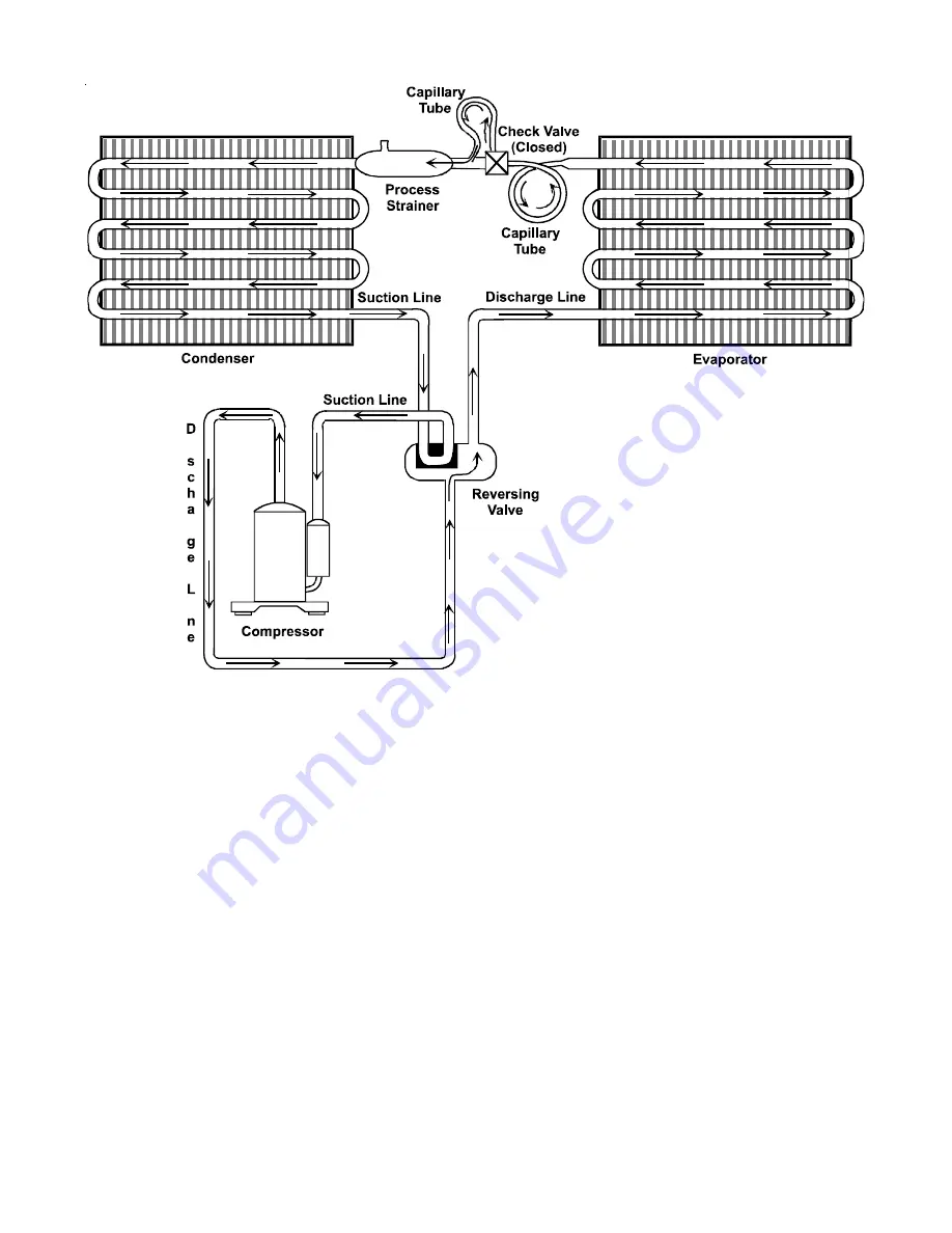
Refrigeration Sealed System - Heat Pump (Heat Pump Mode)
REFRIGERATION SEALED SYSTEM
Page 1: ...served PACKAGE TERMINAL AIR CONDITIONER HEAT PUMP Standard and Remote Applications with LED M70 Control Board and R 410A This manual is to be used by qualified professionally trained HVAC technicians...
Page 2: ...IMPORTANT INFORMATION INDEX PRODUCT IDENTIFICATION 4 IMPORTANT INFORMATION 2 SPECIFICATIONS 5 PROPER INSTALLATION 9 MAINTENANCE 32 OPERATIONS 34 SERVICING 38 WIRING DIAGRAMS 61 ONLY PERSONNEL THAT HA...
Page 3: ...HO ARE UNABLE TO REACT TO THE FAILURE OF THIS PRODUCT THE FAILURE OF AN UNATTENDED AIR CONDITION ER MAY RESULT IN EXTREME HEAT IN THE COND ITIONED SPACE CAUSING OVERHEATING OR DEATH OF PERSONS OR ANIM...
Page 4: ...E Examples 4 265V 60Hz 1Ph A Standard Model PTC073E35AXXX 5 240 220V 50Hz 1Ph C Corrosion Protection Seacoast PTC073E50CXXX D Power Door PTC073E35CDXX E Makeup Air Electric Heater PTC073E35CQVX DESIGN...
Page 5: ...amps Overcurrent protection on 265 volt models must be cartridge style time delay fuses included and factory installed on all Amana brand 265 volt chassis See heater perform EER Energy Efficiency Rati...
Page 6: ...less than 250 volts have a Leak Current Detector Interrupter LCDI pow er cord and meet UL 484 standards 11 Refer to electric heat performance data for total MCA and recommended overcurrent protection...
Page 7: ...omplete model number 8 R 410A refrigerant used in all systems 9 All units meet or exceed ASHRAE90 1 standards 10 All units less than 250 volts have a Leak Current Detector Interrupter LCDI power cord...
Page 8: ...er 8 R 410A refrigerant used in all systems 9 All units meet or exceed ASHRAE90 1 standards 10 All units less than 250 volts have a Leak Current Detector Interrupter LCDI power cord and meet UL 484 st...
Page 9: ...tric heaters is 15 amps Overcurrent protection on 265 volt models must be cartridge style time delay fuses included and factory installed on all Amana brand 265 volt chassis See heater perform EER Ene...
Page 10: ...Wet Coil CFM Dry Coil Ventilated Air CFM Fan Only Dehumidification Pints Hr Notes All 265 volt models must use an Amana brand sub base PTSB4 E or an Amana brand hard wire kit PTPWHWK4 Minimum Circuit...
Page 11: ...3 7 4 9 6 1 715 700 1090 1090 1350 1330 715 1090 1340 COP5 3 4 3 4 3 1 3 2 3 0 3 0 3 4 3 1 3 0 CFM Dry 360 360 410 360 410 410 COP Coefficiency of Performance per AHRI Test Procedures units are rated...
Page 12: ...cify two digit heater kW size to complete model number 8 R 410A refrigerant used in all systems 9 All units meet or exceed ASHRAE 90 1 standards 10 All units less than 250 volts have a Leak Current De...
Page 13: ...ge 1 1 5 1 04 1 27 230 208 1 97 253 265 238 292 Operating Voltages Voltage Utilization Range LCDI or AFCI Power Cords Underwrites Laboratories and the National Electric Code NEC now require power cord...
Page 14: ...met See Minimum Unit Clearances and Minimum Interior and Exterior Pro jections Figures as well as Minimum Clearances and Projections table for details If installed in a concrete or masonry wall a lin...
Page 15: ...ight sleeve corner Extension cords must not be used with the unit See the note on Wall Sleeve Dimensions Fig ure 42 1 4 1075 mm Minimum 16 1 4 415 mm Mini mum Dimension B in Table 1 Minimum Wall Openi...
Page 16: ...sloping to the outside 5 Two holes will need to be drilled in both sides of the wall sleeve for mounting into the wall Drill holes of proper size and in the proper location so the screws will engage...
Page 17: ...ment 2 If a standard subbase is used be sure the right hand subbase cover is removed before the chassis is installed in the sleeve 3 On 230V 30A units installed with an existing subbase use the subbas...
Page 18: ...ation Mode Switches Master Switch The master switch disconnects power to all of the system components When this switch is in the off position the compressor fan motor reversing valve and electric resi...
Page 19: ...of a front desk switch The following figure shows a wiring schematic for connecting the front desk switch to the unit If the unit is configured for wired unrented setback energy management see Configu...
Page 20: ...er to the Maintenance and Cleaning section for the proper cleaning procedure If this light is still on after cleaning please refer to the Diagnostic Sta tus Report section for assistance ON OFF MASTER...
Page 21: ...or must be left closed when the outdoor temperature might fall below freez ing or a power door kit must be installed AIR DISCHARGE GRILLE The discharge grille can be adjusted to expel air at either a...
Page 22: ...ress the OFF key Configuration feature mode will also exit if no keys are pressed for a pe riod of two 2 minutes Refer to the Configuration Chart Wireless Communications PTAC models PT G have the opti...
Page 23: ...ng additional motion sensing Ensure location is out of the path of foot traffic where a person might accidentally bump into the thermostats and damage the device 2 Remove thermostat from mounting plat...
Page 24: ...AND POWERED DOOR SENSOR OPTION In cases where there is no top door frame the sensor will need to be mounted on the wall next to the door In these cases a wired magnet a field supplied single pole sing...
Page 25: ...MUST BE 15 16 FROM THE SENSOR MOUNTING PLATE MAGNET HOLDER MAY EXTEND ABOVE THE DOOR OR THE DD01E OR MAY EXTEND BELOW THE DOOR FRAME TO ENSURE THE MAGNET IS NO MORE THAN 1 8 FROM THE BOTTOM CENTER OF...
Page 26: ...les The door frame and door usually will not align Place holder on the door and select the slot that places the magnet as close as possible to the 15 16 depth from the back of the DD01 mounting plate...
Page 27: ...m of the DD01E will line up with the center of the line of the magnet holder containing the magnet Choose magnet position A B or C to align the magnet 15 16 from the back of the DD01E or DD01F DOOR SE...
Page 28: ...suffix or 02 03 etc To select the room suffix while still in configuration mode press the HEAT key until appears Then press the up and down arrows to select the room suffix Example For the unit servin...
Page 29: ...efault settings configure the device or devices that were bound See the next section for configuration choices NOTE If a wireless device is replaced or added all de vices including those previously bo...
Page 30: ...higher You can verify the software version by starting with the unit in the OFF position and while holding down the and buttons doubleclicktheCOOLbuttonandthenreleaseand pushtheFANbuttonwithinoneseco...
Page 31: ...est leaves room 8 Press HEAT key to scroll to third unoccu pied setback temperature Press either the up or down arrow to the desired third unoccupied set back temperature 9 Press HEAT key to scroll to...
Page 32: ...The dis play alternates between and 00 Use the up and down arrow keys to change 00 to the previously selected security code NOTE The control will not proceed to the next step until the correct code is...
Page 33: ...Scale C Celsius Scale d6 Sensorless Un Occ Time 1 32 18 1 32 18 d7 1st Un Occ Set Back Temp 1 16 2 1 16 2 d8 1st Un Occ Set Back Time 1 5 1 24 1 5 1 24 5 d9 2nd Un Occ Set Back Temp 1 16 3 1 16 3 dA...
Page 34: ...ake filter 1 Grasp each filter by its molded handle located on the front edge of the front below the discharge grill 2 Pull the filter straight up and remove 3 Clean filter with vacuum or with running...
Page 35: ...e are prop erly sealed The wall sleeve s level should also be rechecked Proper leveling for most installations are a bubble tilt to the outside and level from right to left Contact your sales person f...
Page 36: ...ounds Water is picked up and distributed over the coil This improves the efficiency and helps with water removal Water Dripping Water will collect in the base pan during high humidity days This can ca...
Page 37: ...erridden Automatic 2nd Stage Electric Heat Heat Pump Mod els If the room temperature falls to 4 F below the set point temperature the reverse cycle heat pump is shut off and the strip heat is turned o...
Page 38: ...peed for up to 120 seconds The sample fan is aborted if compressor demand is detected To avoid unnecessary sampling the period between samples will be based on specific room conditions The default sam...
Page 39: ...enser Compressor Evaporator Capillary Tube Process Strainer Suction Line Discharge Line Capillary Tube Check Valve Open Reversing Valve D i s c a r e i e Suction Line Refrigeration Sealed System Heat...
Page 40: ...40 OPERATIONS i r i Refrigeration Sealed System Heat Pump Heat Pump Mode REFRIGERATION SEALED SYSTEM...
Page 41: ...in the system is harmless Nothing could be further from the truth Oxygen from moisture plus normal compressor and motor heat reacts chemically with the refrigerant and oil to form corrosive hydrochlo...
Page 42: ...set With the valve on the charging cylinder closed open the manifold valve to the cylinder 6 Evacuate the system to at least 29 inches gauge before opening valve to thermocouple vacuum gauge 7 Contin...
Page 43: ...the sling psychrometer The cooling performance test should not be employed when outside temperatures are 20 below that of the room Best results are obtained when the test is conducted under peak load...
Page 44: ...abinet front must be in place during this test Record supply voltage to unit Operate unit in highest heat setting Record wattage recorded on wattmeter or total amp draw to unit Refer to heating watts...
Page 45: ...il T Temperature Across Indoor Coil T 90 85 80 75 70 HEH073 PMH073 PTH073 HEH074 PMH074 PTH074 HEH093 PMH093 PTH093 HEH094 PMH094 PTH094 HEH123 PMH123 PTH123 HEH124 PMH124 PTH124 HEH153 PMH153 PTH153...
Page 46: ...cleaning the filter or coils does not clear the status code or the code indicates that servicer should be called DIAGNOSTIC STATUS REPORT MODE To enter Diagnostic Status Report mode press and hold th...
Page 47: ...F3 Indoor Ambient Thermistor reads outside the range 20 F to 200 F Y N Replace black Indoor Ambient Thermistor F4 Indoor Coil Thermistor either above or below operating tolerances N Y Replace Red Indo...
Page 48: ...ompressor Test Motor Windings S 17 Compressor Stuck Use Test Cord S 17 Open Control Circuit Test Control Circuit with Voltmeter S 1 Low Voltage Test Voltage S 1 Faulty Evap or Cond Fan Motor Repair or...
Page 49: ...out remove the cover 3 Disconnect the floodback protector wiring or ther mistor from the control board s Indoor Switch termi nals 4 Remove the two screws securing the top screen to the evaporator ass...
Page 50: ...80000 100000 120000 140000 160000 180000 0 10 20 30 40 50 60 70 80 90 100 110 120 130 140 150 160 170 Temperature deg F Resistance ohms THERMISTOR RESISTANCE TEMPERATURE CHARACTERISTIC WARNING 2 Remov...
Page 51: ...CK 1 Remove front cover 2 Remove the two mounting screws one on each side of the control board cover Tilting the control panel out disconnect ribbon connector from control board DO NOT PULL ON RIBBON...
Page 52: ...e ohms Capacitance Check Using a hookup as shown below take the amperage and voltage readings and use them in the formula WARNING LINE VOLTAGE NOW PRESENT Voltmeter Ammeter Capacitor 15 Amp Fuse Capac...
Page 53: ...looking at it and lift the assembly straight up 13 Loosen the set screw on the blower wheel 14 Remove the three screws securing the motor to the housing and remove the motor from the blower wheel 15 D...
Page 54: ...1 With no power remove the leads from the compressor terminals 2 Touch the leads of an ohmmeter to terminals C S start windings and C R run winding Ground Test With no power and compressor leads remov...
Page 55: ...and low side of the system 2 Start the system and run a Cooling Performance Test If the test shows a Below normal high side pressure b Above normal low side pressure c Low temperature difference acros...
Page 56: ...COOLING If the valve fails to change its position test the voltage 230 V or 265 V at the valve coil connector cap while the system is on the HEATING CYCLE WARNING SET THE THERMOSTAT ALL THE WAY COUNT...
Page 57: ...ng the chassis to the wall sleeve 4 Carefully slide chassis out of wall sleeve placing on floor or protected cart ESCUTCHEON CONTROL BOARD CONTROL PANEL 1 Remove front cover 2 Remove the two mounting...
Page 58: ...the compressor suc tion line to protect against potential liquid refrigerant en tering the compressor If refrigerant temperatures are too low the compressor will be cutoff to help protect the com pre...
Page 59: ...lder out side air when needed 6 Filter to assist in keeping the DigiAIR coils cleaner to maintain dehumidification and outside air flow Permanent and washable 7 Vent door is configurable to either be...
Page 60: ...ized when config ured temperatures outside air RH and operating condi tions are met If codes or property ownership mandate that the makeup air is required 100 of the time then the DigiAIR module shoul...
Page 61: ...tral location to thoroughly clean and have them ready for the next filter check 4 Clean filter with vacuum or with running water Reverse this procedure to reinstall the filter 5 Also inspect and clean...
Page 62: ...ll wiring to the heater assembly and re move the assembly 8 Remove the floodback protector or thermistor from the evaporator discharge tube 9 Remove screws holding evaporator to basepan and par tition...
Page 63: ...ERMINAL BOARD BK DANGER HIGH VOLTAGE 24VAC TRANSFORMER 12VA CLASS 2 ONLY ON OFF MASTER SWITCH HEATER 1 HEATER 2 LINE 1 IN1 COM IN2 AUXILIARY C R GL W2 Y W1 B GH REMOTE THERMOSTAT IAT BLACK ICT RED OCT...
Page 64: ...L2 10 10 ALTERNATE INDOOR MOTOR WIRING COM GND INPUT AC TO MOTOR VSTM ID R 485 S VSM EM EVAP MOTOR 1400 1250 1200 1000 L1 MC LOW HIGH ID FAN L2 11 11 REV VALVE LOW 10 Model Starts With High Speed VST...
Page 65: ...date wiring WARNING DigiAIR MAKE UP SOLUTION KIT R YL GY BU BR RD GY TR 1 To MC BU RD PK ALTERNATE HYDRONIC HEAT HEATER 1 HEATER 2 DANGER HIGH MC L1 WH OPTIONAL POWER VENT DOOR TR 2 L1 WH OR 1 2 3 ON...
Page 66: ...Wiring is subject to change Always refer to the wiring diagram on the unit for the most up to date wiring DigiAIR MAKE UP SOLUTION KIT 1 2 3 ON OFF SWITCH S DB R TR 1 R TR 4 DB L1 OPTIONAL AIR DEHUMI...
Page 67: ...giAIR MAKE UP SOLUTION KIT OPTIONAL LIGHTING CONTROL TR 1 To MC R 6 8 7 2 4 3 1 0 BL RD DB 14 S GY OPTIONAL TRANSFER FAN R 6 8 7 2 4 3 1 0 BL RD TR 1 To MC DB 14 S YL 14 Daughter Board Device Switch 1...
Page 68: ...GH HIGH SPEED CM COMP DB EM FC F HPS HTR MC RCCF RVC TR TB VSM VSTM R OUTDOOR FAN MOTOR COMPRESSOR DAUGHTER BOARD EVAPORATOR MOTOR FAN CAPACITOR FUSE HIGH PRESSURE SWITCH HEATER ELEMENT MAIN CONTROL R...
Page 69: ...RED OCT BLUE IHD ORANGE OAT GREEN IDT YELLOW REV VALVE FAN HIGH LOW OD FAN HIGH LOW LINE 2 COMPRESSOR L2 L1 MC 9 BK BK 7 OR RD TB EM FAN MOTOR CM FAN MOTOR TR 1 265 230 S ID OR 13 BK DANGER HIGH VOLT...
Page 70: ...1170 MC OD FAN LOW HIGH L1 L2 10 10 ALTERNATE INDOOR MOTOR WIRING COM GND INPUT AC TO MOTOR VSTM ID R 485 S VSM EM EVAP MOTOR 1400 1250 1200 1000 L1 MC LOW HIGH ID FAN L2 11 11 REV VALVE LOW TYPE A W...
Page 71: ...he most up to date wiring WARNING R YL GY BU BR RD GY TR 1 To MC BU RD PK ALTERNATE HYDRONIC HEAT HEATER 1 HEATER 2 DANGER HIGH MC L1 WH OPTIONAL POWER VENT DOOR TR 2 L1 WH OR 1 2 3 ON OFF SWITCH S L2...
Page 72: ...RAM WARNING Wiring is subject to change Always refer to the wiring diagram on the unit for the most up to date wiring 1 2 3 ON OFF SWITCH S DB R TR 1 R TR 4 DB L1 OPTIONAL FRESH AIR DEHUMIDIFICATION K...
Page 73: ...to change Always refer to the wiring diagram on the unit for the most up to date wiring WARNING OPTIONAL LIGHTING CONTROL TR 1 To MC R 6 8 7 2 4 3 1 0 BL RD DB 14 S GY OPTIONAL TRANSFER FAN R 6 8 7 2...
Page 74: ...124 1500 1350 PTH153 PTH154 1650 1500 PMH153 PMH154 1650 1500 PTC073 PTC074 1350 1170 PTC093 PTC094 1350 1170 PTC123 PTC124 1350 1170 PTC153 PTC154 1650 1500 Outdoor Motor Speed Selection Model Starts...