Amana PGB**C Installation Instructions Manual Download Page 17

17

Cleaning Flue Passages (Qualified Servicer Only)

1. Shut off electric power and gas supply to the unit.

2. Remove burner assembly by disconnecting the gas

line and removing the manifold brackets from the
partition panel.

3. Remove the flue from the induced draft blower and

the collector box from the partition panel.

4. The primary heat exchanger tubes can be cleaned

using a round wire brush attached to a length of
high grade stainless steel cable, such as drain
cleanout cable. Attach a variable speed reversible
drill to the other end of the spring cable. Slowly
rotate the cable with the drill and insert it into one of
the primary heat exchanger tubes. While reversing
the drill, work the cable in and out several times to
obtain sufficient cleaning. Use a large cable for the
large tube, and then repeat the operation with a
small cable for the smaller tube. Repeat for each
tube.

5. When all heat exchanger tubes have been cleaned,

replace the parts in the reverse order in which they
were removed.

6. To reduce the chances of repeated fouling of the

heat exchanger, perform the steps listed in “Start-
up and Adjustment”.

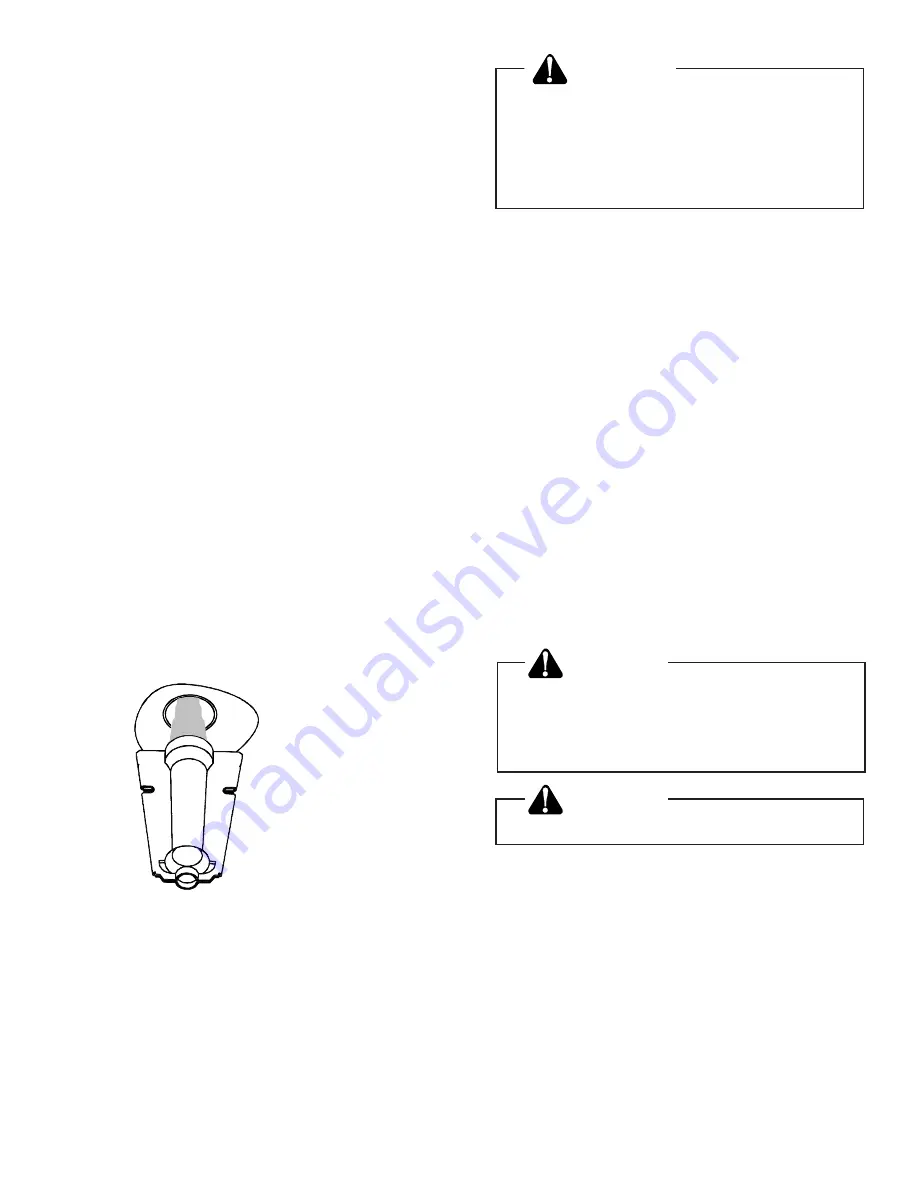
Main Burner Flame (Qualified Servicer
Only)

Flames should be stable, soft and blue (dust may cause
orange tips but must not be yellow). The flames must
extend directly outward from the burner without curling,
floating or lifting off (Figure 15).

Check the burner flames for: 
1. Good adjustment
2. Stable, soft and blue 
3. Not curling, floating, or lifting off. 

Figure 15

Burner Flame

WARNING

To avoid death or personal injury due to
electrical shock, do not remove any in-
ternal compartment covers or attempt
any adjustment. Contact a qualified ser-
vicer at once if an abnormal flame ap-
pearance should develop.

At least once a year, prior to or during the heating
season, make a visual check of the burner flames.

NOTE:  This will involve removing and reinstalling the
heat exchanger door on the unit, which is held by
several screws. If you are uncertain about your ability to
do this, contact a qualified servicer.

If a strong wind is blowing, it may alter the airflow
pattern within the unit enough that an inspection of the
burner flames is not possible.

Cleaning of Burners

1. Shut off electric power and gas supply to the unit.

2. Remove the screws holding the burner retention

bracket in place.

3. Remove the burners.

4. Use a bottle brush to clean burner insert and inside

of the burners.

5. Replace burners and burner retention bracket, in-

spect the burner assembly for proper seating of
burners in retention slots.

6. Reconnect electrical power and gas supply.

CAUTION

Label all wires prior to disconnection
when servicing controls.  Wiring errors
can cause improper and dangerous op-
eration.

CAUTION

Verify proper operation after servicing.

For further information on the yearly inspection, consult
the User Manual. It is recommended that a qualified
servicer inspect and service the unit at least once each
year.

Turn the unit on at the thermostat. Wait a few minutes,
since any dislodged dust will alter the normal flame
appearance. Flames should be predominantly blue and
directed into the tubes. They should not be yellow. They
should extend directly outward from the burner ports
without curling downward, floating or lifting off the ports.

Summary of Contents for PGB**C

Page 1: ...afety practices follow them The precautions listed in this Installation Manual should not supersede existing practices but should be considered as supplemental information ATTENTION INSTALLING PERSONN...

Page 2: ...shut off turn off the manual gas control valve to the unit before shut ting off the electrical supply WARNING To prevent death personal injury or prop erty damage do not use this unit if any part of t...

Page 3: ...rn air entering the unit must be between 50 F and 100 F Provisions must be made for adequate combustion and ventilation air in accordance with Section 5 3 Air for Combustion and Ventilation of the Nat...

Page 4: ...ht bill or indemnity in lieu thereof c Original invoice or certified copy thereof showing trade and other discounts or reductions d Copy of the inspection report issued by carrier representative at th...

Page 5: ...propane gas and for altitude adjust ments Piping IMPORTANT NOTE To avoid possible unsatisfactory operation or equipment damage due to under firing of equipment do not undersize the natural propane ga...

Page 6: ...ring which may result in heat failure This unit and its shut off valve must be disconnected from the gas supply dur ing any pressure testing of that system at test pressures in excess of 1 2 PSIG 3 48...

Page 7: ...er gas pressure depends on three main factors 1 Vaporization rate which depends on a tempera ture of the liquid and b wetted surface area of the container or containers 2 Proper pressure regulation 3...

Page 8: ...re 5 V Electrical Wiring Locating The Thermostat Thermostat should be mounted 5 feet above the floor on a vibration free inside wall in a room or a hallway that has good air circulation Movement of ai...

Page 9: ...sformer primary lead and induced draft blower mo tor leads as shown on the unit wiring diagram Heat Anticipator Setting The heat anticipator in the room thermostat must be correctly adjusted to obtain...

Page 10: ...duct should be provided with an access panel This access should be large enough to inspect the air chamber downstream from the heat exchanger for any smoke or combustion gas leaks A cover should be ti...

Page 11: ...ocated and other spaces of the building Turn on clothes dryers and any appliance not connected to the common venting system Turn on any exhaust fans such as range hoods and bathroom exhausts so they w...

Page 12: ...ll Out Protector Figure 9 Rollout Protection IX Heating Sequence of Operations Normal Sequence of Operation Heating 1 Thermostat calls for heat The combustion blower is immediately energized 2 The pre...

Page 13: ...Figure 12 With Power And Gas On 2 Put unit into heating cycle and turn on all other gas consuming appliances Figure 12 Measuring Inlet Gas Pressure Alternate Method Secondary Limit Control On the PGB...

Page 14: ...per cubic foot as deter mined by Step 2 then Input 1000 x 3600 0 34 106 000 BTU per Hour NOTE BTU content of the gas should be obtained from the gas supplier This measured input must not be greater t...

Page 15: ...ishing phases of construction on a new struc ture This type of use may result in pre mature failure of the unit due to extremely low return air temperatures and expo sure to very dirty atmospheres To...

Page 16: ...d with water thoroughly dried and sprayed with a filter adhesive before being reinstalled Filter adhesives may be found at many hardware stores Permanent filters should last several years However shou...

Page 17: ...sonal injury due to electrical shock do not remove any in ternal compartment covers or attempt any adjustment Contact a qualified ser vicer at once if an abnormal flame ap pearance should develop At l...

Page 18: ...ng Flame Roll Out Switch Blower Motor Gas Orifice Blower Wheel Heat Exchanger Burner High Limit Switch Compressor Secondary Limit Condenser Coil Ignitor Flame Sensor Condenser Fan Blade Induced Draft...

Reviews: