Amana PGB**C Installation Instructions Manual Download Page 12

12

Xl. Startup and Adjustment

Heating Startup

General Information
This unit is equipped with an electronic ignition device
to light the pilot which then lights the burners. It also has
a power vent blower to exhaust combustion products.

On new installations, or if a major component has been
replaced, the operation of the unit must be checked.

Check unit operation as outlined in the following instruc-
tions. If any sparking, odors, or unusual sounds are
encountered, shut off electrical power and recheck for
wiring errors, or obstructions in or near the blower
motors. Duct covers must be removed before operating
unit.

Heat Anticipator Setting
The heat anticipator in the room thermostat must be
correctly adjusted to obtain the proper number of heat-
ing cycles per hour and to prevent the room tempera-
ture from over-shooting the room thermostat setting.
Heat anticipator must be set at 0.4 amps.

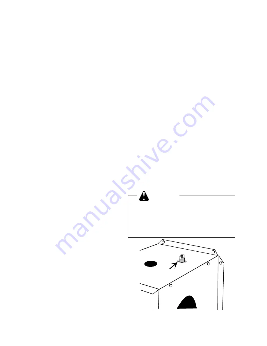
Roll-out Protection Control
If the flames from the burners are not properly drawn
into the heat exchanger, a roll-out protection device will
open, cutting power to the gas valve. The roll-out pro-
tection device is located on the side of burner box
(Figure 9). The reason for elevated temperatures at the
control should be determined and repaired prior to re-
setting this manual reset control.

WARNING

To prevent death, personal injury or prop-
erty damage due to fire or explosion,
before manually resetting the roll-out pro-
tection device, a qualified servicer must
investigate the reason for the roll-out
protection device to open.

Burner

Box

Roll-Out

Protector

Figure 9

Rollout Protection

IX. Heating Sequence of Operations

Normal Sequence of Operation - Heating

1. Thermostat calls for heat. The combustion blower is

immediately energized.

2. The pressure switch contacts transfer.

3. The ignitor is energized and pilot gas begins to flow.

4. After pilot flame is proven, the main valve is ener-

gized and the pilot will light the main burners.

5. The control checks the signal from the flame sen-

sor. Gas flow will continue only if a proper signal is
present. As soon as pilot flame is proven, the ignitor
is de-energized.

6. The unit will continue to fire for 30 seconds. The fan

control will then start the main circulating air blower.

7. The unit will deliver heat to the conditioned space

until the thermostat is satisfied.

8. The gas valve and combustion blower will be de-

energized when the thermostat opens.

9. There is an adjustable Heat Fan OFF of approxi-

mately 60/90/120/150 second delay (factory set at
120). The control module will de-energize the blower
once the selected time has elapsed. This allows
any additional heat in the heat exchanger to be
transferred to the conditioned space.

X. Cooling Sequence of Operations

Normal Sequence of Operations - Cooling

1. Thermostat calls for cooling. The compressor and

outdoor fan are energized.

2. Approximately six seconds later, the indoor fan

starts.

3. The unit will deliver cooling to the conditioned space

until the thermostat is satisfied.

4. The compressor and outdoor fan will be de-ener-

gized when the thermostat opens.

5. The indoor fan continues to run for approximately

30 seconds after the thermostat is satisfied. This
allows additional cooling from the indoor coil to be
transferred to the conditioned space. Then, the in-
door fan stops.

Summary of Contents for PGB**C

Page 1: ...afety practices follow them The precautions listed in this Installation Manual should not supersede existing practices but should be considered as supplemental information ATTENTION INSTALLING PERSONN...

Page 2: ...shut off turn off the manual gas control valve to the unit before shut ting off the electrical supply WARNING To prevent death personal injury or prop erty damage do not use this unit if any part of t...

Page 3: ...rn air entering the unit must be between 50 F and 100 F Provisions must be made for adequate combustion and ventilation air in accordance with Section 5 3 Air for Combustion and Ventilation of the Nat...

Page 4: ...ht bill or indemnity in lieu thereof c Original invoice or certified copy thereof showing trade and other discounts or reductions d Copy of the inspection report issued by carrier representative at th...

Page 5: ...propane gas and for altitude adjust ments Piping IMPORTANT NOTE To avoid possible unsatisfactory operation or equipment damage due to under firing of equipment do not undersize the natural propane ga...

Page 6: ...ring which may result in heat failure This unit and its shut off valve must be disconnected from the gas supply dur ing any pressure testing of that system at test pressures in excess of 1 2 PSIG 3 48...

Page 7: ...er gas pressure depends on three main factors 1 Vaporization rate which depends on a tempera ture of the liquid and b wetted surface area of the container or containers 2 Proper pressure regulation 3...

Page 8: ...re 5 V Electrical Wiring Locating The Thermostat Thermostat should be mounted 5 feet above the floor on a vibration free inside wall in a room or a hallway that has good air circulation Movement of ai...

Page 9: ...sformer primary lead and induced draft blower mo tor leads as shown on the unit wiring diagram Heat Anticipator Setting The heat anticipator in the room thermostat must be correctly adjusted to obtain...

Page 10: ...duct should be provided with an access panel This access should be large enough to inspect the air chamber downstream from the heat exchanger for any smoke or combustion gas leaks A cover should be ti...

Page 11: ...ocated and other spaces of the building Turn on clothes dryers and any appliance not connected to the common venting system Turn on any exhaust fans such as range hoods and bathroom exhausts so they w...

Page 12: ...ll Out Protector Figure 9 Rollout Protection IX Heating Sequence of Operations Normal Sequence of Operation Heating 1 Thermostat calls for heat The combustion blower is immediately energized 2 The pre...

Page 13: ...Figure 12 With Power And Gas On 2 Put unit into heating cycle and turn on all other gas consuming appliances Figure 12 Measuring Inlet Gas Pressure Alternate Method Secondary Limit Control On the PGB...

Page 14: ...per cubic foot as deter mined by Step 2 then Input 1000 x 3600 0 34 106 000 BTU per Hour NOTE BTU content of the gas should be obtained from the gas supplier This measured input must not be greater t...

Page 15: ...ishing phases of construction on a new struc ture This type of use may result in pre mature failure of the unit due to extremely low return air temperatures and expo sure to very dirty atmospheres To...

Page 16: ...d with water thoroughly dried and sprayed with a filter adhesive before being reinstalled Filter adhesives may be found at many hardware stores Permanent filters should last several years However shou...

Page 17: ...sonal injury due to electrical shock do not remove any in ternal compartment covers or attempt any adjustment Contact a qualified ser vicer at once if an abnormal flame ap pearance should develop At l...

Page 18: ...ng Flame Roll Out Switch Blower Motor Gas Orifice Blower Wheel Heat Exchanger Burner High Limit Switch Compressor Secondary Limit Condenser Coil Ignitor Flame Sensor Condenser Fan Blade Induced Draft...

Reviews: