Always
O
n UPS Systems
M0704_NX_Series_Service_Manual V2.17 2012-06-12
9
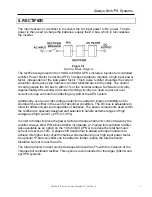
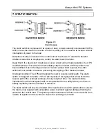
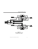
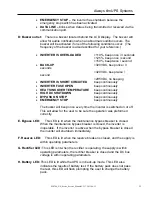
7. STATIC SWITCH
The static switch is composed of two pairs of back to back naturally commutated SCR’s,
which moves the load from inverter to reserve (utility) or from reserve to inverter without
interruption of power to the load.
Detection circuitry is included in the control circuit to achieve “0” dead time transfer.
Additional detection is employed to control the static switch transfer.
Dead Short: If a dead short circuit was to occur under normal mode operation, the UPS
would detect the short circuit and immediately stop the inverter until the problem has
been rectified. Due to the large amount of current a dead short requires, the static
switch will not transfer to reserve preventing the tripping of the reserve breaker.
Overload condition: The UPS will transfer the load to reserve (utility) path. The static
switch is designed to handle 110% of the capacity of the system but will switch to the
reserve path if the overload continues for any length of time. The load will still be
operational, but the load system will not be protected from a utility failure, as it has no
battery capability until the overload is removed.
The static switch will only be activated if the input levels are within parameters to ensure
the load is only supplied with acceptable power to protect against damage that may be
caused to the critical load. The system performs numerous checks on the transfer from
inverter to bypass and visa versa to ensure the exchange is smooth.
Figure 7.1
Static Bypass


