
Always
O
n UPS Systems
M0704_NX_Series_Service_Manual V2.17 2012-06-12
60
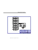
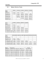
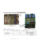
Table 21.1
LED Operation for the 3C PCB
PCB FUNCTION LOCATION
NORMAL ABNORMAL
SOLUTION
PCB LED LED Illumination
Description
LED
Illumination
Description
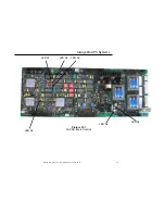
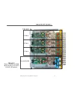
3C
Rectifier Control (It is
separated into 3CC
and 3CD board for the
option of 12 pulse)
PCB Module
LED C1
Yes
Rectifier Enabled
No
PCB has no input
power or input power
outside of operating
parameters
Ensure cable connections are secure
and correctly attached.
Check the input power
Replace the board
LED C2,
C3
All Yes
PCB has power
All No
PCB has no input
power
Ensure cable connections are secure
and correctly attached.
Replace the board
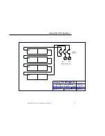
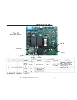
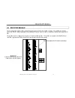
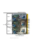
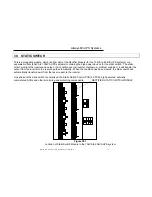
LED C1
LED C2
LED C3
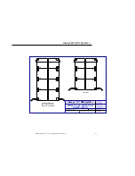
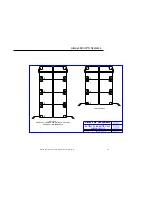
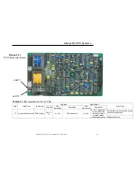
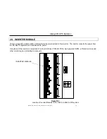
Picture 21.1
3C PCB (6 Pulse Rectifier Driver)
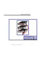
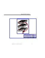
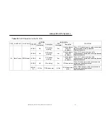
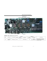
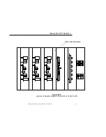
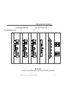
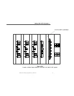
Picture 21.2
3C and 3CC PCB (12 Pulse Rectifier Driver)
LED C1
LED C2
LED C3