background image

INSTALLATION AND OPERATION MANUAL | CUL11 CONTROL UNIT

4

4

PRODUCT DESCRIPTION

The section of electric mains to which the product is connected should be equipped with a pro-

tection device (three-pole circuit-breaker). The distance between terminals in the protective 

cutout device should be at least 3 mm.
Parameters of electric cables used (section, number of wires, length and other) should comply 

with the connection diagram, device power, laying distance, laying method, ambient conditions. 

Use a multicore cable with double insulation.
Electric cables should be protected against contact with any rough and sharp surfaces, use 

corrugated tubes and cable glands for laying cables.

The company reserves the right to change this manual and product construction without prior 

notice, however maintaining the same functionality and purpose.
Instruments and materials used should be complete, in good condition and comply with the 

current safety regulations, standards and instructions.

The company does not directly control the installation of the product and automation devices, 

its maintenance and operation, and cannot be responsible for the safety of product installation, 

operation and technical maintenance.
Recommendations described in this manual should be considered as an example, as the place 

of installation can differ. The task of the installer is to make the most appropriate decision.

The installer is responsible for work on the entire system. In his work, he should observe the cur-

rent regulations and standards (e.g., DIN 1986, EN 12050, EN 1398). He is also responsible for main-

tenance of technical documentation of the entire system that is supplied with the equipment.

The content of this manual cannot be used as grounds for legal challenges.

2. 

PRODUCT DESCRIPTION

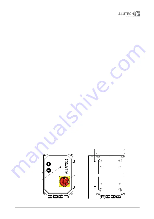
The unit is designed to control components of the transfer equipment. Directly for the transfer 

platform with telescopic (extensible) ramp equipped with 2-valve hydraulic unit. On-off switch

 1 

(

fig. 

1), control buttons 

and 

3

, indication 

LED 4

 are located on the cover of control unit housing.

The control unit is supplied with a cable 5G 1.5 sq. mm for power connection (1 m long / without 

plug). When being manufactured, the dock levellers are fitted with 4G 1 sq. mm cable for con-

nection of the electric motor for the hydraulic unit and two 2 × 1 sq. mm cables with connectors 

for connection of hydraulic unit valves. The Manufacturer chooses the necessary length of the 

cables depending on the size of a dock leveller. The set of cables СTL07-2 consists of 7 m long 

cables. The set of cables СTL10-2 consists of 10 m long cables.

190

28

0

25

4

190

239

180

165

120

1

4

2

3


Figure 1

. Control unit (dimensions are given in millimeters)

Summary of Contents for CUL11

Page 1: ...CONNECTION AND OPERATIONAL MANUAL Control unit CUL11 English 2020 www alutech group com ...

Page 2: ......

Page 3: ...LC reserves the right to change this manual without giving prior notice to customers buyers 2020 ALUTECH Door Systems CONTENT 1 General information and safety measures 3 2 Product description 4 3 Technical specifications 5 4 Electric module 5 5 Operation test and commissioning 8 6 Operation 9 7 Faults and recommendations on their elimination 10 8 Storage transportation and disposal 11 9 Warranty l...

Page 4: ......

Page 5: ...th this require ment can lead to product damage cause its malfunction fire and other hazardous situations When installing and operating there should be no foreign objects or liquids inside the product otherwise disconnect the product from mains supply and contact the service department Op erating the product in this state is unsafe The control unit is to be installed with cable glands downward to ...

Page 6: ... should be considered as an example as the place of installation can differ The task of the installer is to make the most appropriate decision The installer is responsible for work on the entire system In his work he should observe the cur rent regulations and standards e g DIN 1986 EN 12050 EN 1398 He is also responsible for main tenance of technical documentation of the entire system that is sup...

Page 7: ...ected fig 2 is located inside the control unit List of module elements Element Element Description Description FU1 T10А500V fuses CAUTION Use quartz sand filled fuses FU2 FU3 FU4 T2А500V fuse CAUTION Use quartz sand filled fuse FU5 T3 15А250V fuses FU6 FU7 HL1 LED indicating the operation of control buttons 2 and 3 fig 1 Lights up when the control button is pressed HL2 LED indicating the electric ...

Page 8: ...ff and control unit does not operate For control unit operation OUT 24 V and IN 24 V contacts should be closed NC J8 Connector for connection of hydraulic unit valves fig 6 and door position sensor fig 8 If the sensor is triggered the electric motor of hydraulic unit turns off and the dock leveller starts lowering J9 Connector for connection of the jumper to select an output type of door position ...

Page 9: ...L2 L1 PE PE J3 BU GY BK BN 1 3 5 2 4 6 YE GN Figure 2 Electronic module J3 J1 J2 HPT OUT N L3 L2 L1 PE PE HPT IN J6 3 400V J4 N LL LAMP FU7 FU6 FU5 3 T3 15A250V FU3 FU1 FU2 3 T10A500V 24V KEY4 LED 24V 24V KEY2 24V KEY3 KEY1 J10 VAL2 VAL1 24V GND GND GND VAL3 DAT J8 HL7 HL6 HL5 HL4 2 6A 3 2A 3 8A 4 4A 5A 5 6A 6 2A 6 8A 7 4A 8A 8 6A 9 2A J12 J5 W V U MOTOR IN OUT 24V LED J13 HL1 HL2 HL3 NC NO PNP NP...

Page 10: ...VAL3 DAT J8 V1 V2 24V KEY4 LED 24V 24V KEY2 24V KEY3 KEY1 LED NO NO RD BU J10 VAL2 VAL1 24 GND GND GND VAL3 DAT J8 PNP NC BN BK BU PNP NPN J9 NO NC J13 VAL2 VAL1 24 GND GND GND VAL3 DAT J8 NC PNP NPN J9 NO NC J13 VAL2 VAL1 24 GND GND GND VAL3 DAT NC PNP NPN J9 NO NC J13 A B C Figure 6 Valves connection Figure 7 Connection of control buttons and LED fig 1 J4 N LL LAMP 230V max100W J5 J3 W V U PE PE...

Page 11: ...as performed any first action control button is pressed door position sensor is activated and switches off when the power is turned off If the lamp does not light up then it is not connected or has failed If the lamp stops lighting during platform operation the fault is detected section 7 Faults and recommendations on their elimination 6 After successful completion of trial cycles the leveller sho...

Page 12: ...position in order to return the leveller to the initial position press and hold control button 2 fig 1 until the leveller lifts and the lip returns into the initial position retracts back release button and after 2 seconds the leveller automatically lowers into the initial position switch the on off switch 1 fig 1 to 0 position OFF position The scheduled maintenance of the control unit should be p...

Page 13: ...f the door position sensor is connected check whether the door is open Make sure that the sensor is connected and operational check the state change of sensor LED LED goes dim or lights up when the sensor is triggered Check the setting of jumpers in J9 and J13 connectors When pressing or button HL1 LED does not light up the dock leveller does not move Control buttons are not connected or failed Ma...

Page 14: ...er or from the date of manufacture if the date of delivery is unknown 3 Manufacturing faults that occur during the warranty period are eliminated by the service department that performs warranty maintenance Note parts replaced under the warranty become the property of the service department that performed the product repair 4 Warranty on the product is not valid in the following cases violation of...

Page 15: ...le for the installation signature print name Consumer Customer has verified the completion agreed and accepted warranty conditions and terms and has no claims against the product appearance The product is installed and ad justed in accordance with the established requirements and qualified for operation Consumer has been provided with information on existing hazards and risks as well as rules on o...

Page 16: ...ble for the repair signature _________________________________________________ print name Repair contractor information Repair operations list Date of repair Signature of the person L S responsible for the repair signature _________________________________________________ print name Repair contractor information Repair operations list Date of repair Signature of the person L S responsible for the ...

Page 17: ...INSTALLATION AND OPERATION MANUAL CUL11 CONTROL UNIT 15 15 SPECIAL NOTES ...

Page 18: ......

Page 19: ......

Page 20: ...Арт R7090139 04 2019 10 Selitskogo str 220075 Minsk Republic of Belarus Tel 375 17 330 11 00 Fax 375 17 330 11 01 www alutech group com ...

Reviews: