- 2 -
PT2724
Overview:
Altronix PT2724/PT2724E is an extremely versatile two channel 365 Day 24 Hour Timer/Controller designed
to support a wide range of applications. Such applications include: Home and Building Automation, Security,
Access Control, Lighting Control, etc.
The timer is equipped with two independently controlled form “C” relay contact that provide many latching and/
or momentary operations during a program schedule of your choice. The EE-Prom memory allows for program-
ming of unit prior to or during field installation. Events may be set for single or multiple operations on a daily
and/or weekly schedule. The block programming feature enables repeating an event on any combination of
consecutive days. PT2724 will compensate for daylight savings time if desired. It automatically adjusts for leap
year and individually selected holiday exceptions can be programmed to override regularly scheduled events.
Specifications:
Input:
• 12 to 24 VAC or VDC operation.
Relay:
• Two (2) form “C” relay contacts are rated
10A @ 120VAC/28VDC.
• Standby current: 10mA (relay off),
50mA (relay on).
• Tandem relay mode allows both channels
to activate simultaneously for all events.
Features:
• EE Prom memory protects against loss of
programming due to power failure.
• Accurate crystal controlled clock.
• Momentary and/or Latching Events.
• 50 individually programmed daily/weekly events.
• Block programming capacity can accommodate
a total of 350 events per week.
• 10 programmable Holiday dates per channel.
• “First man in” option.
Features
(cont’d)
:
• Standard or Daylight Savings Time settings.
• Automatic compensation for leap year.
Visual Indicators:
• Alphanumeric LCD display
simplifies programming.
Battery Backup:
• Built-in charger for 12VDC sealed lead acid
or gel type batteries
(Max charge current 100mA).
• Optional lithium battery backup maintains
clock. Order Altronix part # LB2032.
Mechanical:
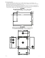
•
PT2724 - Timer module.
Board Dimensions (approx.):
5.25” x 3.6” x 1” (133.4mm x 91.4mm x 25.4mm).
• PT2724E - Timer module in enclosure.
Enclosure Dimensions (H x W x D approx.):
8.5” x 7.5” x 3.5” (215.9mm x 190.5mm x 88.9mm).
Installation Instructions:
1. Mount PT724A/PT724AE/DPT724A in desired location.
Carefully Review:
Basic Operation
(pg. 3)
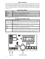
Terminal Identification Table
(pg. 3)
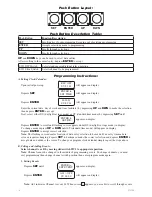
Push Button Layout and Description
(pg. 4)
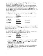
Programming Instructions
(pg. 4-7)
2. Connect 12 to 24 volts AC or DC to terminals marked [+ DC – / ~ AC ~].
When using DC carefully observe polarity.
3. Connect 12VDC battery (optional) to terminals marked [+ BAT – / 12VDC].
4. Insert lithium battery (optional/not included. Order part LB2032) in battery holder (Fig. 1, pg. 3)
with the + positive side facing up.
5. Connect devices to be controlled to dry relay outputs marked [NO, C, NC] of either Channel A or Channel B.
Note: It is important when connecting DC powered electromechanical devices such as Mag Locks,
Electric Strikes, Bells, Relays, etc. to install a catch diode across the pos (+) and neg (–) terminals of
the device. Connect diode as close to the device as possible with the banded side facing the pos (+)
terminal. This will reduce the possibility of interference.
6. Program clock and desired event schedule (see programming instructions pg. 4-7).


