background image

24 

AlterG Installation Manual 


105440 rev C 


Bag Installation 


1.


Unroll bag. The inside of the bag is 

black, the outside is gray. 


COLD WEATHER WARNING:  

If the bag has 

been exposed to cold weather it must acclimate 
to room temperature before unrolling.  The clear 
vinyl windows can crack if unrolled while cold.  
At 70°F (21°C) the bag should warm for 2 hours.  
If the bag is “resistant” to unrolling, stop and 
wait longer for the bag to warm up.   


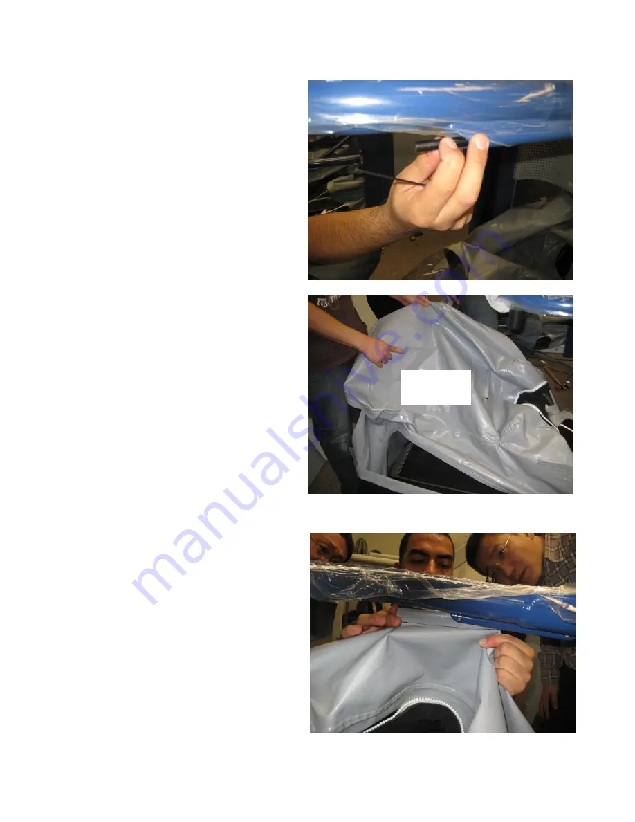
2.


The bag attaches to 4 points on the 

cockpit.  Remove the short rods from 
the tubes that serve as the 
attachment points.  Loosen one of the 
retaining screws and remove the rod. 


3.


Position the bag over the treadmill. 

Two black cones sewn to the top of 
the bag identify the front and a large 
pocket sewn behind the access hole 
identifies the rear. 


4.


Attach the top of the bag to the 

cockpit.  There are 4 short hems sewn 
to the bag around the perimeter of the 
hole.  These hems are captured in the 
4 corresponding tubes. Slide a rod into 
the hem, and then insert the assembly 
into the corresponding tube on the 
cockpit. Replace and tighten the 
retaining screws. 


Large pocket 
at rear of bag 

Summary of Contents for Anti-Gravity M320 Stride Smart

Page 1: ...1 AlterG Installation Manual 105440 rev C AlterG Anti Gravity Treadmill M300 Series Installation Manual ...

Page 2: ... and understand these instructions and statements before servicing the AlterG Anti Gravity Treadmill NOTE The AlterG Anti Gravity Treadmill has been tested to IEC medical standards for electrical safety It is a Class I Type B device Type B Medical Equipment RoHS compliant product IEC 60601 1 1 compliant IEC 60601 1 2 compliant IPX 0 AlterG and Anti Gravity Treadmill are registered trademarks in th...

Page 3: ...n 9 Moving the AlterG System to a Location 9 Removing the AlterG from the Pallet 9 Removing the AlterG from the Dollies 9 Preparing the System for Operation 10 ASSEMBLY INSTRUCTIONS FOR THE DISASSEMBLED UNIT 12 Moving the AlterG 12 Unpacking 12 Base Assembly 15 Installing the Stanchion Assembly 16 Installation of the Cockpit 18 Installation of the Cable Guide 20 Diagnostic Mode 22 Check Drive Belt...

Page 4: ...l 105440 rev C ALTERG COMPONENT IDENTIFICATION These photos identify the major components and nomenclature used in the assembly of the AlterG system Exterior Components Front cover Side cover Cockpit Bag Stanchion Caps Stanchion ...

Page 5: ...5 AlterG Installation Manual 105440 rev C Interior Components PDU Blower Valve Muffler Modesty Panel ...

Page 6: ... lifting pin 1 4 drive ratchet wrench 9 16 6 or 12 point 1 4 drive socket 1 16 5 64 1 8 5 32 3 16 1 4 7 32 Allen wrenches These are available in most Allen wrench sets 3 16 7 32 1 4 Allen sockets for 1 4 drive ratchet wrench 7 16 1 2 open end or combination box wrench 1 4 5 16 nut drivers Adjustable wrench Right angle 2 Phillips screwdriver 2 Regular slotted screwdriver Small pair of diagonal cutt...

Page 7: ...h Quantity 8 6 8 6 4 Application Stanchion to Base Stanchion to Rails Rails to Base Stanchion to Rails Stanchion to Base Assembly Torque 20 ft lb 19 Nm 12 ft lb 16 Nm 20 ft lb 19 Nm 12 ft lb 16 Nm 12 ft lb 16 Nm Type Socket Buttonhead Socket Flathead Socket Buttonhead Socket Flathead Socket Buttonhead Socket Buttonhead Size 1 4 20 x 3 8 6 32 x 1 2 6 32 x 3 8 20 x 3 4 6 32 x 1 4 8 32 x 1 2 Quantity...

Page 8: ...ht minimum 96 244 cm Note Place the right front corner of the system within 8 feet of the power outlet Electrical Requirements A dedicated 20 Amp 220V circuit with a NEMA 6 20 receptacle required within eight feet of the front right corner of the AlterG Anti Gravity Treadmill Single Phase NEMA 6 20R Receptable Voltage across A and B 200 240VAC ...

Page 9: ...ns The stanchions tie into the base frame and can withstand the loads Note This is a multiple person task The object is to slide the AlterG System off so that the front and rear frame members rest on the middle of their respective dolly Position the first dolly in front heaviest portion of the machine and to the side and slide the system onto the dolly Place the second dolly in back and slide the ...

Page 10: ...counterweight cables are in the pulley grooves as in the image below stanchion caps are shown removed for clarity 2 On each inner stanchion wall there is a bolt as pictured below Use a box or socket wrench to loosen and remove the bolt and washer These bolts and washers can be discarded upon removal Counterweight bolt ...

Page 11: ...own all exterior surfaces 6 Get inside the bag and confirm wire routing to the treadmill is properly secured and clears any moving parts of the treadmill 7 Perform a visual check of treadmill location on the base Confirm that the treadmill is centrally placed side to side and that the side rails of the treadmill are parallel with the side rails of the base 8 Check wall voltage The M310 M320 will o...

Page 12: ...g the pallet for placement of the dollies Unpacking 1 Unscrew and remove the wooden shipping frame Note Use care when removing the frame to avoid scratching any of the underlying components 2 Inspect unit for damage after unwrapping before moving Take photos of any damage 3 Leave protective wrapping on stanchion covers rails etc as long as possible 4 Remove the counterbalance weights and set aside...

Page 13: ... cockpit weights about 95 lbs 43 kgs It is recommended that two people carry the unit Note Use good lifting technique when moving the cockpit 7 Remove the load cell cables from the interior of the treadmill motor cover Note be very careful when operating around these cables to avoid damaging them Caution You may be injured or damage the product if you fail to follow the procedures and safety tips ...

Page 14: ... it 9 Carry the base to its final location The power cord is 10 feet in length Place the front right corner of the base within 8 feet of the electrical outlet to provide slack for cord routing Within 8 feet of outlet Load cell cables exit here Caution You may be injured or damage the product if you fail to follow the procedures and safety tips outlined in this document ...

Page 15: ...e support should be centered in the restraint front to back and side to side It should not bind in the restraint 4 Ensure the front elevation wheels of the treadmill are properly oriented between the front guides on the base and that they are sitting squarely on the load cells Note The wheels should not ride up on the top of the guides 5 Remove the blue tape from each corner of the base and pull o...

Page 16: ...ion location Note If the site does not allow use of a dolly or similar moving aid the assembly can be moved by hand When moving by hand have plenty of help and lift the unit only by the stanchions Lifting by any other component of the assembly can result in damage to the unit 3 Place the stanchion assembly over the treadmill base Note Lower it in from the top or bring it in from the rear to avoid ...

Page 17: ...stanchion should be bolted to the frame with two 5 16 18 socket cap screws They are inserted through the cutout in the base of the stanchion Do not tighten at this time 6 Bolt the front side rails to the base using two 3 8 x 16 socket cap screws on both sides You may have to look through the outer clearance hole of the rail to line up the inner rail hole with the threaded hole in the base Do not t...

Page 18: ...he cockpit in the stanchions 3 The cockpit weighs about 95 lbs 43 kg Use two people one on either side of the cockpit Lift the cockpit and insert the bearing carriages into the top of stanchions ensuring that aluminum pads are aligned to fit into channels Note The cable guide will be sticking out in front of the cockpit make sure it does not catch on the modesty panel when the cockpit is lowered 4...

Page 19: ...se Loctite 242 on the threads 6 Seat the counterweight cable in the pulley 7 Lower the counterweight while maintaining tension in the cable Align the counterweight so that the tapped hole faces inward 8 Move the cockpit over its full range from top to bottom checking to make sure it operates smoothly ...

Page 20: ...nd all cross bars are snapped shut 3 Snap cable guide to the lower bracket on the bottom of the power box Ensure that the cables are routed straight out of the bracket 4 Move load cell cables to outside of machine and all other cables to inside of machine 5 Connect the load cell cables exiting from the cable guide to the corresponding cables coming from the base The load cell cables are labeled Ma...

Page 21: ...fy this cable and plug it into the four pin connector J1 on the bottom of the power box Zip tie it to the strain relief tab provided Blower cable shown unplugged for clarity 8 Take the treadmill power cable that is already plugged into the treadmill and temporarily plug it into the power box 9 Connect the treadmill signal cable coming from the treadmill PCB to its corresponding cable coming from t...

Page 22: ... the display should read 0 3 Place the system in the diagnostic mode by simultaneously pressing the Weight and keys The display will change from 0 to an error code 4 Press START The treadmill display will become active and it can now be operated Check Drive Belt Tension 1 Remove the treadmill motor cover Check all cable connections Check the drive belt tension Pinch the belt midway between the pul...

Page 23: ...s of the treadmill To move the belt left tighten the right bolt turn and loosen the left bolt turn Wait 30 seconds and readjust if necessary Tighten the left bolt turn and loosen the right bolt turn to move the belt to the right Check Treadbelt Tension 1 Walk jog on the treadmill with heavy footfalls Uneven belt speed or sudden stopping of the belt is an indication that the treadbelt is too loose ...

Page 24: ...4 points on the cockpit Remove the short rods from the tubes that serve as the attachment points Loosen one of the retaining screws and remove the rod 3 Position the bag over the treadmill Two black cones sewn to the top of the bag identify the front and a large pocket sewn behind the access hole identifies the rear 4 Attach the top of the bag to the cockpit There are 4 short hems sewn to the bag ...

Page 25: ...emove the quick release pin and reducer Then put the reducer inside the bag pushing it out through the large bag cone Connect the reducer to the valve fitting aligning the holes and re inserting the quick release pin 6 Use the specified rubber strip and hose clamp to secure the bag cone around the ABS reducer just below the quick release pin ...

Page 26: ...nect the treadmill signal cable to the corresponding cable coming from the cable guide 9 Each cable has a thin band of heat shrink to mark the location of clamping see step 10 10 The pressure tube has an elbow joint at the end with a steel tube protruding from the joint Insert the steel tube through the bag port so that the elbow is flush with the top of the port Place a rubber strip around the po...

Page 27: ...s centered 12 Pull the bag over the treadmill and align the hem with the grooves in the base 13 Start at one of the sides and push the bag hem into its corresponding groove 14 Insert the short pointed rod into the hem capturing the hem in the groove 15 Push the rod through tucking the hem into the groove ahead of the rod Using Tri Flow lubricant and twisting the rod while you push will help it sli...

Page 28: ...the bag does not slide in the groove keep the bag centered You may need to use a soft tipped hammer to get the last bit through 18 The end of the rod should align with the end of the groove in the base 19 Insert the remaining side rod followed by the back and front rods following the same procedure Follow with properly sized rod ...

Page 29: ...o the stanchions and the base 2 For all handrails align braces and begin installing screws The rail to stanchion connections use a 5 16 24 socket flathead while the rail to base uses 3 8 18 socket cap screws Do not tighten any of the screws until all handrails are in place and fastened 3 Use the 20 x 3 8 screws and flat washer to connect the rear handrails Rails ...

Page 30: ...ross threading screws 5 Tighten all bolts that were previously left snug Do not exceed the torque specs as outlined on page 7 of this manual a Stanchion to base socket flathead screws b Stanchion to base socket cap screws c Front rail to base cap screws d Rail to stanchion socket flathead screws e Rail to base socket cap screws f Rail to rail buttonhead socket screws ...

Page 31: ... to the power switch on the front panel 3 Attach the main power cable to its mating connector on the underside of the power box see silkscreen on the box to identify cable connector pairs 4 Secure the main power cable to the welded lug located on the inside of the right front rail Use the padded clamp provided Place the clamp 10 feet 3 meters from the plug end of the cable ...

Page 32: ...Install the front cover Align the cutouts in the plastic panel with the pins on the inside of the front rails Push the panel towards the cockpit and then push down until you feel the pins engage the cutouts Push the bottom of the panel in so that the Velcro squares adhere 3 Install the stanchion covers These each use seven 6 32 x 1 4 socket buttonhead screws ...

Page 33: ...the stanchion caps These each use two 6 32 x 3 8 socket flathead screws 5 Insert the plastic plate in the pocket on the top rear of bag 6 Insert the nickel plated caps in the holes in the rails and on the front and rear of the base There are 10 caps total ...

Page 34: ...tallation Manual 105440 rev C Congratulations You re finished installing the AlterG M300 treadmill Turn the system on put on some shorts and test out the unit for 15 minutes to ensure that everything works properly ...

Reviews: