


20
We reserve the right to modify technical specifications without prior notice.
UK830304/190326
© Alpha-InnoTec GmbH
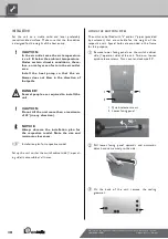
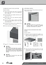
Proceed as follows:
Hang the control element's hooks on the recesses
of the front facade (either in the upper or lower
recesses)...
Example:
Control element in upper recesses
Push the control element down until it locks into
position...
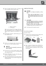
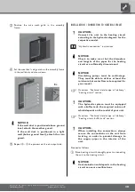
Stick the heating and heat pump regulator's control
cable into the
right
bushing on the bottom of the
control element...
NOTICE.
A connection to a computer or a network
can be installed via the left bushing on the
bottom of the control element, allowing
the heating and heat pump regulator to be
controlled remotely. One pre-condition is
that a screened network cable (category
6) be installed through the unit when
installing the unit.
Operating manual for the heating and heat pump
regulator, version "Qualified technician", “Web
server” section.
If this network cable is available, insert
the network cable's RJ-45 plug into the left
bushing of the control element.
NOTICE.
The network cable can be exchanged at
any time. In order to be able to connect it,
the screen must first be removed.
Installation and removal of the
screen
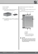
INSTALLING THE SCREEN
NOTICE.
The screen is provided at the time of
delivery so that the control element may
be inserted in the upper recesses of the
front facade.
If the control element has been inserted in
the lower recesses of the front facade, you
must first remove the screen's temporary
cover and then reinsert it above the logo.


