


10
We reserve the right to modify technical specifications without prior notice.
UK830304/190326
© Alpha-InnoTec GmbH
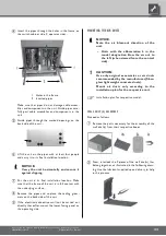
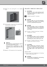
LIFTING THE UNIT WITH PIPES
The units can be lifted with
3
/
4
" and/or 1" pipes (provided
by customer) that are suitable for the weight of the
respective unit. Special holes are provided in the frame
for this purpose.
Remove lower facing panels on the switch cabinet
side (= operator side) of the unit. To do so, loosen
quick-release screws. Turn counter-clockwise 90°...
1 Quick-release screws
2 Lower facing panel
Pull lower facing panel upwards and outwards,
detach and set securely to the side...
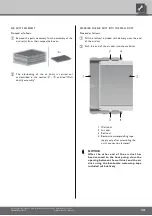
On the back of the unit, remove the sealing
grommet...
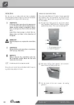
INSTALLATION
Set the unit on a stable, solid and level, preferably
sound-insulated surface. Make sure that the foundation
is designed for the weight of the heat pump.
CAUTION.
In the air outlet area the air temperature
is ca. 5 K below the ambient temperature.
Under certain climatic conditions, there-
fore, an ice layer can form in the air outlet
area.
Install the heat pump so that the air
blower does not blow in the direction of
footpaths.
DANGER!
Several people are required to install the
unit.
CAUTION.
Do not tilt the unit more than a maximum
of 45° (in any direction).
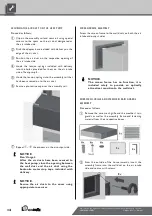
NOTICE.
Always observe the installation plan for
the respective model. Note the size and
minimum clearances.
Installation plan for respective model.
Set up the unit so that the switch cabinet side (= operat-
ing side) is accessible at all times.


