


18
We reserve the right to modify technical specifications without prior notice.
UK830304/190326
© Alpha-InnoTec GmbH
t
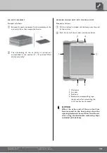
Cut out the rubber sockets on the facing panel...
For positioning of the rubber sockets for insert-
ing the wires, see "dimensional drawing" for the
respective model.
t
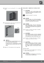
Insert the cables through the rubber sockets in the
unit...
The wires inside the unit are guided in a closed wire
duct to the terminals on the switch plate.
Install electric connections according to the termi-
nal diagram that applies to your model...
Terminal diagram for respective model.
CAUTION.
Ensure clockwise rotary field of the load
power supply (compressor).
– An incorrect rotary field of the
compressor during operation can
cause serious, irreparable damage to
the compressor.
CAUTION.
Make sure to equip the power supply of
the heat pump with a 3-pole automatic
cut-out with at least 3 mm contact gap.
Note the level of the release current.
Overview “Technical data / scope of delivery”,
“Electric” section.
NOTICE.
Factory setting for the electric heating
element in units with integrated electic
heating elements is 6 kW (9 kW). It can
be changed at contactor for 2 (3) or 4 kW
(6kW).
For further information, see the adhesive label
on the electric heating element.
NOTICE.
Using a suitable network cable, the
control element of the heat and heat
pump regulator can be connected with
a computer or a network allowing the
heating and heat pump regulator to be
controlled from there.
Electrical connections
Observe the following when performing all work:
DANGER!
Danger of fatal injury due to electric
shock!
Electrical connections may be installed
only by qualified electricians.
Before opening the unit, disconnect the
system from the power supply and secure
it from being switched back on!
DANGER!
Observe the relevant EN-, VDE and/or
applicable local safety regulations during
installation and during all electrical work.
Comply with any technical connection re-
quirements laid down by the responsible
power supply company!
NOTICE.
All live wires must be stripped before they
are installed in the cable duct of the switch
cabinets!
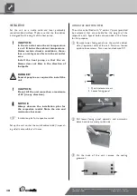
POWER CONNECTION
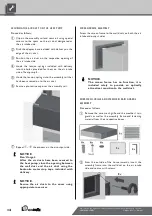
If the unit is closed, open the facing panels on the
operating side...
"Installation".
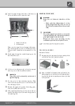
Open electrical switch cabinet of unit...
Example of open
electrical switch cabinet...
Lead 230 V power cable, power cable for circulat-
ing pumps and cable for external temperature sen-
sor through the rubber sockets on the facing pan-
el in the unit...


