


11
We reserve the right to modify technical specifications without prior notice.
UK830304/190326
© Alpha-InnoTec GmbH
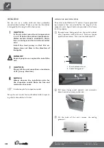
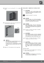
Insert the pipes through the holes in the frame on
the switch cabinet side (= operator side)...
1 Holes in the frame
2 Inserted pipes
Make sure that pipes do not damage cable assem-
blies and components in the unit. Guide pipes care-
fully past cable assemblies and components in the
unit...
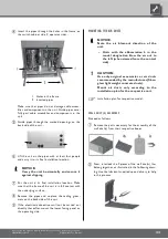
Guide pipes through the marked openings on the
back side of the unit...
Lift the unit on the pipes with at least four people
and carry it to its final installation location...
NOTICE.
Carry the unit horizontally and secure it
against slipping.
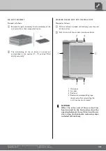
Put the unit in its final installation location. Make
sure that the frame of the unit is in full contact with
the underlying surface...
Remove the pipes and re-place the sealing grom-
mets on the back side of the unit...
If the electrical connections will not be carried out
directly thereafter, mount the lower facing panel on
the operating side.
MOUNTING THE AIR DUCTS
NOTICE.
Note the air blow-out direction of the
unit.
– Units with the abbreviation L in the
model designation blow the air out to
the left (when viewed from the control
side).
CAUTION.
Use only original accessories or air ducts
recommended by the manufacturer (fibre-
glass lightweight concrete ducts).
Mount air ducts only according to the
installation plan for the respective unit.
Installation plan for respective model.
WALL DUCT(S) ASSEMBLY
Proceed as follows:
Remove the parts necessary for the assembly of the
wall duct(s) from their respective boxes...
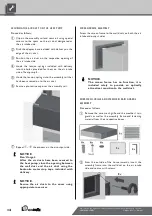
Next, interlock the 2 pieces of the wall duct(s) that
belong together, as illustrated in the following draw-
ing. Use the lubricant supplied upon delivery to help
in this process...


