


16
We reserve the right to modify technical specifications without prior notice.
UK830304/190326
© Alpha-InnoTec GmbH
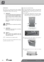
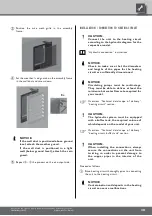
CONDENSATE DISCHARGE
The condensation water that accumulated from the air
must be drained via the pre-mounted hose in the unit
for condensate discharge. To do so, connect the hose
for condendate discharge with a water drain.
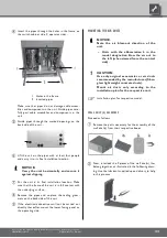
For positioning of the connection for conden-
sate discharge, see dimensional drawings for the
respective model.
1 Hose for condensate discharge
in interior of unit
2 Connection for the condensate
discharge on the outside of the unit
CAUTION!
Guide the pre-mounted hose in the unit
for condensate discharge in the interior of
the unit as a siphon, as shown in the illus-
tration.
Discharge of the condensate into the sewage system is
permitted only via a funnel siphon, which must be acces-
sible at all times.
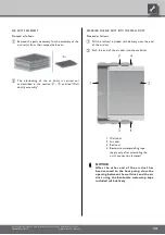
Install shut-off devices for the hot water outflow
(forward flow) and hot water inflow (return flow)
on the heat pump side.
NOTICE.
During installation of the shut-off devices,
the liquefier of the heat pump can be
flushed, if necessary.
CAUTION!
The condenser may be flushed only by
customer service personnel authorised by
the manufacturer.
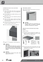
Connect the unit to the pipes of the heating cir-
cuit via vibration decouplers. They must be installed
in order to prevent damage from vibrations to the
pipes.
NOTICE.
Vibration decouplers are available as
accessories.
The connections for the heating water outflow (forward
flow) and the hot water inflow *(return flow) are marked
accordingly.
For positioining of the connections, reference
the dimensional drawing for the respective
model.


