Tri Power X33 Mod HP Manual | Rev 1.20 | © Alpha Technologies GmbH 2013
17
Operating
a
nd Main
tena
nce
Manua
l
Tri Power X33 Mod HP
2.4
Communication devices
The first of the two RS232 serial ports used on the uninterrupted power supply unit and called „maintenance interface“
is located at the top behind the front door. It is dedicated exclusively to diagnostic functions and updating machine firm-
ware.
The second, called „user interface“, is at the top at the back of the UPS. Using this port , with either a computer or speci-
fic network card, it is possible to access UPS operating data and to control the unattended shutdown of the operating
system.
The uninterrupted power supplies of the UPS Tri Power X33 Mod HP family have 2 RS 232 serial ports, 1 relay interface
and 1 output on a 15-pin male D connector logic level interface.
The default setting of the relay interface contacts is Normally Open (NO) but can be configured as Normally Closed (NC)
via the UPS display. Additinally there is available an E.P.O. input terminals.
The indications available with this interface are the following:
Running on battery
Autonomy reserve
Generic alarm
Overload
Bypass activ
Limit values Interface/Features
The techncal specifications of the relay contacts are the following:
V
MAX
= 250VAC - 30VDC, I
MAX
= 5A
E.P.O.-Input
Voltage on open contact: 12V, current with closed contact: 5mA
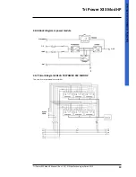
For contact numbering (factory setted)
G
H
ATTENTION
For security reasons the following voltages are tolarated by the interface:
- Maximum voltage between 2 individual cables, which are connected to the interface or beween a cable an
ground must be below 42V at peak or below 60Vdc;
- The isolation voltage of connected cables to the interface should be 1500Vac.
2.4.1 RS232
2.4.2 Relay interface/EPO
PIN
FUNKTION
1-2
Running on battery
3-4
Autonomy reserve
5-6
Generic alarm
7-8
Overload
PIN
FUNKTION
1-2
Bypass activ
3-4
E.P.O.
5-6
-


