ADM-SDEV-BASE/XCKU060 User Manual
V1.0 - 27th November 2018
3.1.1 Switch Definitions
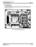
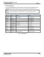
There is a sliding switch situated on the bottom right corner of the board, plus a set of eight DIP switches and a
push button switch placed on the top right corner of the board. Their functions are described in
Switch
Definitions
.
Note:
All switches are OFF by default. Factory Configuration switch must be in the OFF position for normal
operation.
Switch Ref.
Function
ON State
Off State
SW1 (push
button)
Reset
System Reset
Normal Operation
SW2-1
Reserved
-
Normal Operation
SW2-2
Reserved
-
Normal Operation
SW2-3
Config Disable
Configuration of the FPGA is disabled. Normal Operation.
SW2-4
FPGA User 1 -
FPGA Bank 64
User defined
User defined.
SW2-5
FPGA User 2 -
FPGA Bank 24
User defined
User defined.
SW2-6
Reserved
-
Normal Operation
SW2-7
Factory
Configuration
-
Normal Operation
SW2-8
Reserved
-
Normal Operation
SW3 (sliding)
POWER ON/
OFF
PSU ON (position A)
PSU OFF (position B)
Table 2 : Switch Definitions
Page 5
Functional Description
ad-ug-1360_v1_0.pdf


