


7
7
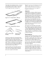
To determine a flow resistance correction factor
for use with similar diffusers and duct
configurations, use the volume rates as determined
from the duct traverses both with and without the
hood as follows.
V
hood
= Flow rate with the hood in place
V
no hood
= Flow rate without the hood in place
CF =
V
no hood
/V
hood
V
measured
= Volume rate as displayed by the
capture hood
V
corrected
= Volume rate corrected for the flow
resistance of the capture hood
V
corrected
= CF x V
measured
Temperature
The temperature readout on the APM 150 meter
indicates general trends in the air temperature
coming from a diffuser. The Electronic Balometer
has a temperature sensor located inside an
aluminum housing behind the meter. Because of
the mass of the housing, the Electronic Balometer
will show a lag in temperature reading from actual
if the air temperature is changing. The time
response of the temperature channel depends on
the amount of flow passing through the Balometer.
For flows under 200 CFM (100 l/s, 340 m
3
/h), the
temperature time response is in the order of
minutes. For fast measurements of air flow
temperature, the Alnor 175 or 275 probe is
recommended. To compare the temperature
reading of the Electronic Balometer to a standard,
the air flow temperature must remain constant to
within 0.25 degrees C.
Atmospheric Pressure
Above 500 CFM (250 l/s, 850m
3
/h), large changes
in atmospheric pressure can affect readings from
the Balometer. The correct value is inversely
proportional to the atmospheric pressure. A
change in atmospheric pressure of –3% will
require the display to be multiplied by +3%. See
Appendix E for additional information.
Note:
When using the Balometer, make sure that a
complete seal is made around the diffuser. Any
leaks will cause measurable errors.
Attaching the Optional Probes (175,
275 and 220B)
Refer to page 9 on removing the meter from the
base.
To attach the probe for measuring air velocity:
!
Make sure the meter is off before attaching or
detaching a probe.
!
Remove the protective cap from the probe and
save for restoring the probe later.
!
Attach the 12-pin connector on the probe to
the probe port on the meter.
!
Turn the connector clockwise to tighten.
Depending on the connected sensing device, you
will have a choice of available units.
Sensing Device
Available Units
Balometer Hood
l/s, m
3
/h, cfm, °F, °C
ThermoAnemometer
Probe
l/s, m
3
/h, cfm, kmh,
m/s, mph, fps, fpm, °F,
°C
220B Relative
Humidity Probe
RH, °F, °C
Clearing the Memory
If this is the first time you are using the APM 150
meter, clear the memory before using the
instrument.
Clearing the memory is done with the following
steps:
• Push
CLR
until [
] appears.
• Push
↑
until [
] appears.
• Push
↵
to clear memory.
The meter starts in
RUN
mode. It will display
measurement values associated with the unit last
used. If the value is OVERRANGE the display
will show [
]; similarily if the instrument is
measuring an UNDERRANGE value the display
will show [ ].
Summary of Contents for APM 150
Page 1: ...Electronic Balometer with APM 150 Meter OWNER S MANUAL...
Page 4: ......
Page 26: ...22 22...
Page 76: ......