


6
6
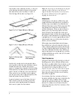
The number 1 and 5 channels also have a wing nut
at the straight end which will mate with an angle
and studs on the ends of numbers 2, 5 and 6 to
form the longer frame sides (see Figure 13).
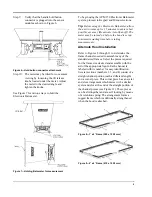
Figure 10—1' x 5' Frame (305 mm x 1525 mm)
Figure 11—3' x 3' Frame (915 mm x 915 mm)
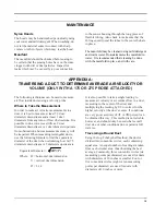
Figure 12—Frame corner
assembly
Figure 13—Frame
side assembly
Each hood is constructed in a trapezoidal shape,
sewn together so that one open end forms a square
attachment to the base, and the other forms a
square or rectangle large enough to fit its matching
frame assembly. Around each end of the hood, an
elastic “shock” cord has been sewn into the hood.
This cord is of a size such that it can be pushed
into the open side of the U-shaped channels of the
frame and around the top of the base.
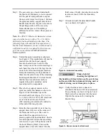
In general, attach a hood to the frame first, and
then to the base unit. By stretching around the
corners the cord is slightly reduced in diameter
and is easier to press into the channel.
Note:
The hood corners should always be aligned
with the corners of the base, near the hood
support brackets. The base has rivets located in
the corners which can be used as a guide for
aligning the hood corners.
Standards
All Balometers or hoods are calibrated to some
standard. Different manufacturers or calibration
facilities may use standards or methods that are
different from those used at TSI Incorporated. TSI
uses laminar flow elements as the standard to
calibrate Balometers. These are devices that are
made up of a very fine honeycomb mesh. The
pressure drop across a laminar flow element is
approximately linear with the flow going through
the element. Alnor Balometers are calibrated using
a standard two by two foot square diffuser. Other
manufacturers may use orifice plates or nozzles
and may not use a diffuser.
When using proportional balancing techniques,
these differences will not be important. However,
when comparing Balometers against other hoods,
or when comparing Balometers calibrated at TSI
with other calibration facilities, these differences
may be important. It is not unusual to see air flow
calibration differences on the order of 5% because
of different standards.
Flow Resistance
All capture hoods cause flow resistance on the air
handling system. Just as different diffuser styles
have their own characteristic flow resistance, so do
capture hoods. This added resistance reduces the
true amount of air exiting the diffuser.
In the
majority of cases, this error is less than or equal
to the accuracy of the instrument.
Proportional
balancing techniques will also assist in making
these effects negligible.
To determine if the flow resistance effects are
important, perform duct traverses to determine the
volume rate exiting a diffuser both with and
without the capture hood in place. The difference
between the volume rate with and without the
capture hood in place is the flow resistance effect
for that diffuser.
Summary of Contents for APM 150
Page 1: ...Electronic Balometer with APM 150 Meter OWNER S MANUAL...
Page 4: ......
Page 26: ...22 22...
Page 76: ......