


9
Series AE1L, AE.E, AE.N, AE.H, AE.V, AED1E, AED2N
Design ID, ZD
the joint oil, refer to the disassembly and assembly in-
structions.
7.1.2.2 Bearing of the drive shaft and lubrication of the
bearings
Bearing of the drive shaft in the bearing bracket
through re-greasable angular contact and groove ball
bearings.
Note:
The groove ball bearing is greased for life with
vertical pump installation.
Roller bearing lubricants
We recommend the following roller bearing lubricants
or others of a proven similar quality for lubricating the
ball bearings. The sequence of manufacturers is no
quality rating.
Manu-
facturer
Brand
Name in acc.
with DIN 51825
Agip
Agip GR MU3
K3K-20
ARAL
Aralub HL3
K3K-20
BP
BP Energrease LS3
K3K-20
ESSO
BEACON 3
K3N-30
Fuchs
RENOLIT FWA 220
K3N-20
Klüber
MICROLUBE GL 263
K3N-20
Mobil-Oil
Mobilux 3
K3K-20
Shell
Shell Alvania Grease R3
K3N-30
SKF
SKF Grease LGMT3
K3K-30
If none of the above roller bearing lubricants are
available, we recommend using a multi-purpose lubri-
cant on lithium basis in any case, which corresponds
to one of the above DIN names.
The mixing of greases with different basic oils and
thickeners leads to reduced lubricating properties and
should therefore be avoided.
The table in Chapter 7.1.2.6 shows the allocation of
the pump sizes to the amount in grease per gram.
Relubrication period
The bearings must be relubricated each 4,000 operat-
ing hours.
Relubrication
Relubrication takes place via the lubricating nipple
(119) screwed into the bearing bracket (110). Con-
tinue regreasing until the old grease emerges from
the bearing cover (131). Scrape the old grease off.
7.1.2.3 Shaft sealing
Shaft sealing either takes place via a stuffing box or a
mechanical seal.
•
Stuffing box
Possibly increased leaks on the stuffing box during
the first operating hours normally decrease on their
own during the warm-up time.
If necessary, slightly tighten the hexagon nuts (202)
on the gland (203).
Please observe that there has to be a slight leak on
the stuffing box. This dissipates the friction heat that
forms on the sealing surface.
If the leaking losses increase disproportionately and if
this cannot be reduced by slightly tightening the
hexagon nuts (202) several times, the packing rings
have lost their shape elasticity and must be replaced.
!
Dismounting the old packing rings and clean-
ing the stuffing box casing
After relieving the pump from pressure and re-
moving the gland, you can take out the old pack-
ing rings. Use a packing puller with elastic shaft.
Afterwards, carefully clean the stuffing boxspace
and the drive shaft in the area of the packing
rings. Used-up drive shafts respectively shaft pro-
tection casings must be renewed (see disassem-
bly and assembly instructions).
!
Installing the packing rings
As a rule, you may only install
packing rings that correspond to
the required operating conditions of the pump.
The dimensions and required number of pre-
pressed packing rings and ring cuts respectively
cut lengths are listed in the table in Chapter
7.1.2.6.
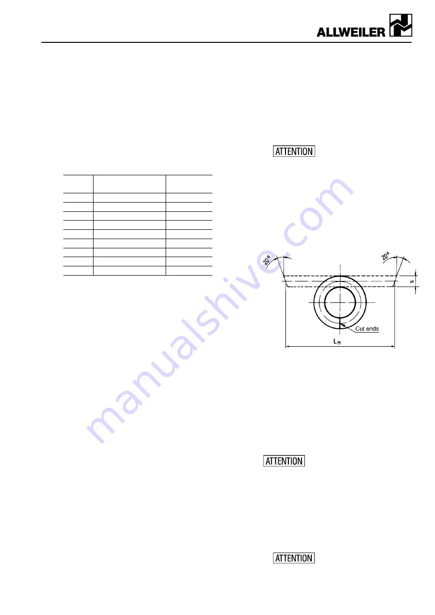
With cuts
we recommend the straight vertical cut
to the shaft. In order to achieve a gap-free, paral-
lel position of the cutting ends when closing the
packing ring, the cutting angle should be approx.
20° to both cut ends (see figure 1).
Figure 1: Cutting packing rings
Pre-pressed packing rings or ring cuts
have to be
carefully turned open axial and radial so that they can
just about be slid across the shaft. Bending the rings
may lead to damages.
When installing in the packing space, carefully rebend
the packing rings to ring shape. The cutting joints
have to be shifted by 90° here. Each ring has to be
slid into the Stuffing boxspace individually with the
cutting ends facing forward by means of the gland.
The sealing chamber ring or flushing ring have to be
installed sequentially.
You may never use pointed objects
for this work. Danger of damaging
the shaft and deforming the packing material!
!
Start-up the stuffing box after re-packaging
The stuffing box may only be tightened slightly
prior to start-up. When starting the pump, 50 to
200 drops per minute are an admissible leakage
quantity.
During the warm-up process of approx. 30 min-
utes, adjust a minimum leakage of 2 to 20 drops
per minute by evenly tightening the gland (203)
step by step via the hexagon nuts (202).
The stuffing box temperature
may not rise abnormally during
this process. Approx. 20° to 60°C above the con-
veyor liquid temperature are admissible. In case