


19
Series AE1L, AE.E, AE.N, AE.H, AE.V, AED1E, AED2N
Design ID, ZD
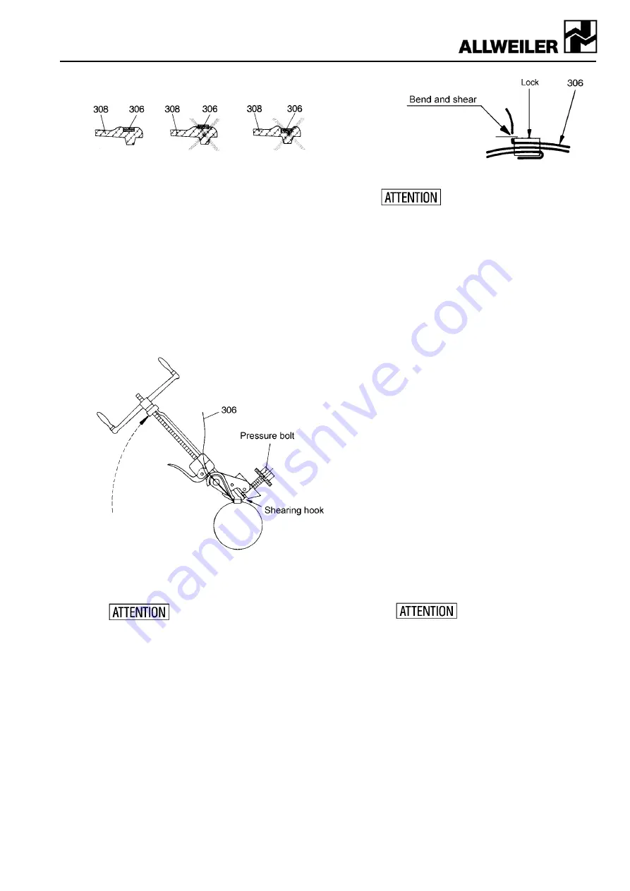
Right Wrong Wrong
Joint clamp (306)
has slightly
drawn in the
outer collar form
and has a tight
fit.
Joint clamp (306)
is too loose and
may slide off.
Joint clamp (306)
too tight. Collar is
damaged
(stripped off).
Figure 14: Tightening the joint clamps
!
Check that the joint clamp (306) is positioned in
the joint collar (308) across the entire circumfer-
ence in the collar groove.
!
Slowly turn the clamping tool by approx. 60° up-
wards until the shear hook reaches behind the
joint clamp lock (see figure 15).
!
Tighten the pressure screws by hand until the joint
clamp has a tight fit.
Figure 15: Shearing the joint clamp
!
Turn the pressure screw with a spanner or ratchet
clockwise until the joint clamp is sheared off.
If the joint clamp is lifted up
slightly on the sheared off side,
adjust this by careful realignment. Do not hammer
or hit on the joint clamp lock, otherwise you may
damage the collar.
Note:
Joint clamps made of hastelloy cannot be
sheared off with the clamping tool. After canting at
the joint clamp lock, shear off the joint clamp with
a pair of metal shears and deburr the cutting
edges (see figure 16).
•
Clamping with the clamping tool PoK-It II
!
When using the clamping tool PoK-It II, cant the
joint clamp (306) after tightening on the joint
clamp lock by swiveling the clamping tool in such
a way that the clamp cannot slide back through
the lock. After canting at the joint clamp lock,
shear off the joint clamp with a pair of metal
shears and deburr the cutting edges (see figure
16).
Figure 16: Canting and shearing the joint clamp
Check whether the joint clamp is bent
in such a way that it cannot slide
back through the joint clamp lock (see figure 16). If
this is not the case, remove the joint clamp and re-
place it with a new one.
7.2.2.5 Installing the joint shaft and the drive-side joint
!
Attach the drive-side joint to the drive shaft (118)
as described in Chapter 7.2.2.4.
!
Slide the joint shaft into the joint cup of the drive
shaft (118).
!
Secure the joint collar (304) as illustrated with a
puncher blow.
!
Pull on the joint collar (308), fill the joint cavity with
joint oil and attach the joint clamps as described.
!
Insert the g
asket for suction casing
(501).
!
Slide the suction casing (505) across the rotor
(401). Make sure that the finely crafted rotor is not
damaged here.
!
Attach the suction casing (505) with the hexagon
screws (606), the serrated lock washers (608) and
the hexagon nuts (607) on the bearing bracket
(110).
Note:
Prior to tightening hexagon nuts (607), align
the connection flange of the suction casing (505).
Observe the proper position of the connections in
the stuffing box (204) respectively mechanical
seal housings (214). See our fitting dimension
sheets.
7.2.2.6 Installing the stator
!
Slide the O-ring (513) and reducer flange (512), if
provided, into the suction casing (505).
!
Prior to pulling on, grease the stator (402) and ro-
tor (401) with lubricant (silicone oil, polydiol, soft
soap or similar).
Do not use any normal oil.
!
With stators made of plastic or metal, insert stator
seals (403) and (404).
Note:
With stators made of plastic, the stator seal
(403) with the O-ring must always lie on the outlet
side.
!
With multi-part stators (402) pull on the stator
(402) with the center hole or center groove point-
ing towards the support (612) onto the rotor (401).
Note:
In case of difficulty, turn the stator (402)
with pliers at the same time. To do so, arrest the
drive shaft (118).
!
With multi-part stators, turn the stators (402) in
such a way that the fixing pieces (631) reach into
the groove respectively boring of the stators (402).
!
Slide the support (612) (if provided) onto the
clamp bolts (611).
!
Screw the pressure casing (504), support (612), if
provided, stator (402) and suction casing (505)
together with the clamp bolts (611) and the hexa-