14
15
4. Assemble the Frame
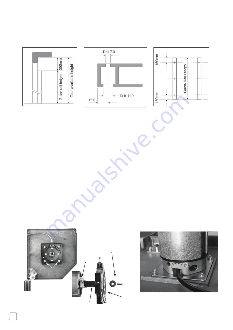
3.2.2 Drill Fixing Holes
Drill holes through 7mm diameter & counter drill 11mm diameter as shown as shown in
Fig 8.
A minimum three holes per rail are required as shown as shown in
Fig 9.
NB
position holes for best fixing to brickwork.
4.1 L/H or R/H Motor (Factory Fitted as Standard)
The motor and control unit can be mounted on either the L/H side or R/H side. (Please specify at time of order).
All AlluGuard doors are fitted with a safety brake as standard excluding AG55 Doors shown in
Fig 10
.
• If you want to change the hand of the motor this should be carried out by a suitably trained engineer.
• If you do move the Motor & Safety Brake ensure that these are installed correctly otherwise the unit will not
activate under normal running conditions.
• It is important that the head plates are securely fixed – 3 fixings per head plate.
4.2 End Plates and Safety Brake Device* (Safety brake factory fitted as Standard)
Lay the Head assembly on the ground, parallel with and just inside the garage opening.
Ensure the motor is situated at the correct end for your installation and that the motor limit adjusters are at the
top/bottom as shown in
Fig 11
.
Fix the motor plate to the end plate by using four M6 x 25 countersunk screws and Nyloc nuts provided.
Fig 7
Fig 8
Fig 9
20mm M6 Bolt
& Washer
2x10mm nuts
& washers
Shaft
Safety Break
Safety Collar
Dummy End
Fig 10
Fig 10a
Fig 11
Summary of Contents for AG55
Page 11: ...11 ...
Page 23: ...23 EMR Exterior Release Kit Installation Instructions ...


