Camera interfaces
190
Prosilica GT Technical Manual V3.2.0
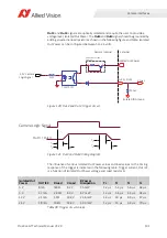
Out1 and Out2 (Non-isolated)
Out 1
and
Out 2
signals are not electrically isolated and can be used when
environmental electrical noise is insignificant and faster trigger response is
required. Tie signal ground to Camera GND to complete the external circuit. The
output signal is a low voltage TTL, maximum 3.3 volts. It is not suitable for driving
loads in excess of 50 µA.
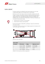
Out3 and Out4 (Opto-isolated)
Figure 119: Out 1 and Out 2 trigger circuit
Note on 4.75 K
Ω
resistors
Prosilica GT Technical Manual
V2.1.1, V2.2.0, and V2.3.0 presented two 4.75 K
Ω
internal pull-down resistors in the opto-isolated output trigger circuit. In July 2012,
these 4.75 K
Ω
resistors were removed from the printed circuit board assembly.
Regardless of whether your Prosilica GT camera has the two 4.75 K
Ω
internal
pull-down resistors or not, implement the output trigger (Out3 and Out4) as
described later.
3.3
V
Camera Logic
Out 1 / Out2
Camera Internal E
x
ternal
3.3
V
4.
7
5 K
DMN3404L-
7
3.3
V


