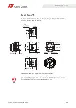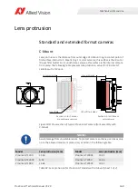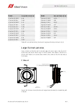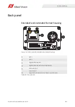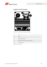
Mechanical dimensions
178
Prosilica GT Technical Manual V3.2.0
PA mounts
Prosilica GT cameras allow planarity adjustment of the mount relative to the
camera sensor. Adjustment can be made for overall flange focal distance (Z
distance), and planarity (Z-tilt). The following steps describe Z adjustment using a
standard EF lens and a target. However, measurement tools such as an optical
depth micrometer could also be used.
1.
Using a compatible lens, set the lens to infinity and image on a target (10 to 15
meters). Target should highlight focus levels at center image and at the
corners of the image. A lens with a long focal length, or adjustable zoom lens,
allows more precision for this operation and reduce the overall size of your
target.
2.
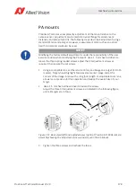
Use a 1.5 mm hex ball head driver to loosen the screws.
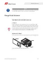
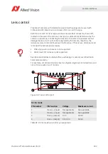
Adjust the three tilt adjustment screws, as indicated in the following figure,
until all targets are in focus.
3.
Tighten the three screws and recheck the focus.
NOTICE
Modifying the factory default adjustment is under the responsibility of the user.
Exercise caution when modifying the PA mount. Use a 1.5 mm hex ball driver to
loosen the three spring loaded screws, adjust the tilt adjustment screws as
required, then secure the set screws.
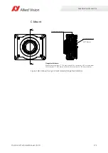
Figure 111: Back view (left) and exploded view (right) of Prosilica GT1930L camera
assembly showing the adjustment screws and screws in the EF-Mount
A
djustment Screw
x
3
Screw
x
3

