Allied Telesis AT-S41 User Manual Download Page 168

AT-S41 User’s Guide

168

Viewing the AT-S41 Switch Information

The procedure in this section explains how to display general 
information about the switch.

To display the switch information, perform the following procedure:

1. Click on the General Info menu tab and select Switch Info from the 

sub-menu.

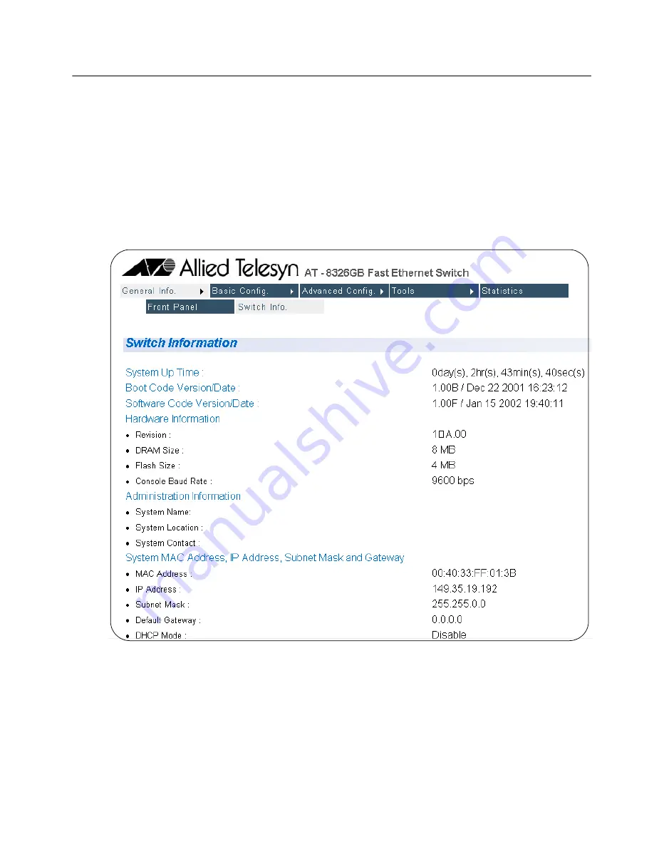
The Switch Information page will be displayed, as shown in Figure 
52.

Figure 52  

Switch Information Page

There are not any configuration options on this page; it is for 
informational purposes only. 

Summary of Contents for AT-S41

Page 1: ...Management Software AT S41 User s Guide FOR THE AT 8326GB FAST ETHERNET SWITCH VERSION 1 0 PN 613 50283 00 Rev B...

Page 2: ...in are trademarks or registered trademarks of their respective owners Allied Telesyn Inc reserves the right to make changes in specifications and other information contained in this document without p...

Page 3: ...ng Management Software Updates 14 Section I Overview 15 Chapter 1 Management Software Overview 16 Local Management Session 18 Telnet Management Session 19 Web Browser Management Session 20 SNMP Manage...

Page 4: ...n 47 Bootstrap Configuration 49 Chapter 5 Port Parameters 52 Configuring Port Parameters 53 Configuring Gigabit Port Type 56 Chapter 6 Port Security 58 Port Security Overview 59 Configuring Port Secur...

Page 5: ...fault 113 Setting the VLAN Type 114 Chapter 11 MAC Address Table 115 MAC Address Overview 116 Displaying MAC Addresses 118 Viewing MAC Addresses by Port 120 Viewing the MAC Addresses by MAC 121 Viewin...

Page 6: ...y Strings and Trap IP Addresses 164 Resetting the Management Software Default Values 166 Rebooting a Switch 167 Viewing the AT S41 Switch Information 168 Ping Execution 169 Bootstrap Configuration 171...

Page 7: ...6 Viewing the MAC Addresses of a VLAN 218 Adding Static MAC Addresses 220 Deleting Static MAC Addresses 221 Chapter 26 Quality of Service 222 Configuring QoS 223 Chapter 27 IGMP Snooping 225 Activatin...

Page 8: ...ty Configuration Menu 61 Figure 17 Intrusion Detection Status Menu 64 Figure 18 Port Trunk Example 1 67 Figure 19 Port Trunk Example 2 68 Figure 20 Trunk Configuration Menu 69 Figure 21 Port Monitorin...

Page 9: ...e 178 Figure 59 Configuration of a Port 179 Figure 60 Statistics Window 181 Figure 61 Port Security Page 184 Figure 62 Port Security Overview Page 186 Figure 63 Trunk Configuration Page 188 Figure 64...

Page 10: ...ers in this section explain how to manage a switch from a local management session or a Telnet management session A local management session is established by connecting a terminal or PC to the RS 232...

Page 11: ...conventions Note Notes provide additional information Warning Warnings inform you that performing or omitting a specific action may result in bodily injury Caution Cautions inform you that performing...

Page 12: ...b based Guides The Allied Telesyn Web site at www alliedtelesyn com contains PDF files of the Installation and User Guides for all Allied Telesyn products The documents can be viewed online or downloa...

Page 13: ...com You can use the Knowledge Base to submit questions to our technical support staff and review answers to previously asked questions E mail and Telephone Support For Technical Support via E mail or...

Page 14: ...AT S41 User s Guide 14 Obtaining Management Software Updates New releases of management software for our managed products can be downloaded from the Allied Telesyn web site http www alliedtelesyn com...

Page 15: ...rs in this section provide an overview of the AT S41 management software on the AT 8326GB Fast Ethernet switch They review the different methods for accessing the management software and describe the...

Page 16: ...security The AT S41 management software comes pre installed on the switch with default settings for all of its operating parameters The default settings may be adequate for some networks and may not n...

Page 17: ...erent types of management sessions that you can use to access the AT S41 management software on an AT 8326GB Fast Ethernet switch They are Local Management Telnet Web Browser SNMP This chapter briefly...

Page 18: ...This type of management session is referred to as local because you must be physically close to the switch such as in the wiring closet where the switch is located Once the session is started you wil...

Page 19: ...previous section Once you have established a Telnet management session with an AT 8326GB master switch that has an IP address you have complete management access to all of the other AT 8326GB switche...

Page 20: ...r type of remote management just as a Telnet management session is considered remote because any workstation on your network that has a Web browser can be used to manage an AT 8326GB stack Note For in...

Page 21: ...nt method requires loading the AT 8326GB Fast Ethernet switch MIBs into the SNMP management program For instructions refer to your SNMP management documentation The AT S41 software supports the follow...

Page 22: ...Chapter 2 Stacking This chapter explains the stacking features of the AT 8326GB switch The sections in this chapter include Stacking Overview on page 23 Stacking and the Management Software on page 2...

Page 23: ...P addresses you need to assign to the switches you are managing since you can use one IP address for all of the switches in a stack You assign the IP address to the master switch of the stack Note You...

Page 24: ...session on the master switch you are by default addressing that particular switch The management tasks that you perform effect only the master switch unless you select another switch in the stack usin...

Page 25: ...on page 32 Chapter 5 Port Parameters on page 52 Chapter 6 Port Security on page 58 Chapter 7 Port Trunking on page 65 Chapter 8 Port Monitoring on page 73 Chapter 9 Spanning Tree Protocol on page 79 C...

Page 26: ...gement Session This chapter contains the procedures for starting local and Telnet management sessions on an AT 8326GB Fast Ethernet switch The sections in this chapter are Local Management Session on...

Page 27: ...your network Additionally running a local management session does not interfere with the flow of Ethernet traffic through the unit When you start a local management session on an AT 8326GB stack you c...

Page 28: ...a Stack ID of 1 The STACK ID LEDs on the front of the switches will tell you which is the master switch of the stack Figure 1 Connecting a Terminal or PC to the RS232 Terminal Port 2 Connect the other...

Page 29: ...al Management Session The switch then displays the management software s Main Menu as shown below Figure 3 AT S41 Main Menu Local Management Session To select a menu item type the corresponding letter...

Page 30: ...hed managing a switch This can prevent unauthorized individuals from making changes to a switch s configuration should you leave your management station unattended Note You cannot operate both a local...

Page 31: ...application protocol You can assign an IP address during a local management session For instructions on how to start a local management session refer to the previous section of this chapter Note For...

Page 32: ...8326GB Switch Need an IP Address on page 33 Configuring an IP Address on page 34 Configuring System Administration Information on page 36 Setting the User Interface Configuration on page 38 Activating...

Page 33: ...rkstation This gateway address is the IP address of the router through which the stack and management station will communicate You do not need to assign an IP address subnet mask or gateway address if...

Page 34: ...m IP Configuration Menu 3 Change the parameters as desired To change a parameter type the bracketed letter in the corresponding command and when prompted enter the new information The commands for cha...

Page 35: ...specifies the default router s IP address This address is required if you intend to remotely manage the stack from a management station that is separated from the stack by a router Enable Disable D H...

Page 36: ...e 4 Figure 5 System Admin Configuration Menu 3 Change the parameters as desired To change a parameter type the bracketed letter in the corresponding command and when prompted enter the new information...

Page 37: ...configuration procedures on the wrong stack Set System L ocation This command specifies the location of the stack This parameter is optional and may contain up to 50 characters Set System C ontact In...

Page 38: ...parameter type the bracketed letter in the corresponding command and when prompted enter the new information The commands for changing the parameters in the User Interface Configuration Menu are desc...

Page 39: ...the switch The user name can be from 0 to 12 characters in length and can consist of alphanumeric characters a to z A to Z and 0 to 9 The same user name is used for both local and remote management s...

Page 40: ...gement feature on the stack and so prevent individuals from managing the stack remotely using an SNMP agent Enable Disable W eb Server This command allows you to disable the Web browser management fea...

Page 41: ...always assign the same IP address to the stack when the stack is reset or powered on If you choose dynamic the server will assign an unused IP address from its list of potential IP addresses each tim...

Page 42: ...ame The maximum length for a read community name is 20 characters Set SNMP W rite Community This command specifies the SNMP write community The parameter can be set to private or public M odify SNMP T...

Page 43: ...ceiver This command allows you to add an SNMP trap receiver The range is set of 1 to 4 D elete SNMP Trap Receiver This command deletes a specified SNMP trap receiver E nable Disable Authentication Tra...

Page 44: ...the Switch Tools Configuration Menu type R to select System Reboot The System Reboot Menu is displayed in Figure 8 Figure 8 System Reboot Menu 3 From the System Reboot Menu type O and then select Fac...

Page 45: ...s the switch to its factory default settings If you select this option all of your configuration changes will be erased Factory Default Except IP Resets the switch to its factory default settings exce...

Page 46: ...neral Information Menu There are no configuration options on this page it is for informational purposes only AT 8326GB Local Management System Main Menu General Information System up for 01hr s 38min...

Page 47: ...is command specifies the IP address of the end node you are pinging Set N umber of Requests Number of ping attempts the switch should make before it stops pinging if it does not receive a response The...

Page 48: ...enu with ping test results is displayed in Figure 12 Figure 12 Ping Results The number in the results display designates the number of the ping attempt For example No 1 represents the first ping attem...

Page 49: ...prompted enter the new information The commands are described below Set B oot Load Mode Allows the user to determine how the stack should boot up There are two boot load options local and remote Loca...

Page 50: ...f of successfully TFTP The stack will use the IP address it had prior to reboot to download the image file from the server through TFTP using the information configured in Switch Tools Software Upgrad...

Page 51: ...s a file that contains all of the existing configurations and settings for a stack You can upload the configuration file and modify the stack settings and then download the configuration file back to...

Page 52: ...apter contains procedures for viewing and changing the parameter settings for the individual ports on a stack This chapter contains the following procedures Configuring Port Parameters on page 53 Conf...

Page 53: ...up number A number in this column indicates that the port is a member of a trunk AT 8326GB Local Management System Basic Switch Configuration Port Configuration Menu Stack ID 1 Port Trunk Type Link St...

Page 54: ...e it from unauthorized connections Possible values are Enabled The port is able to send and receive Ethernet frames This is the default setting for all of the ports on the switch Disabled The port has...

Page 55: ...configure port mode type M to select the Set Mode option The following prompt is displayed Set Mode Enter port number Port number is in range of 1 to 26 0 to set all ports Except giga port Enter a po...

Page 56: ...I to choose Select Stack ID and enter the ID number of the switch in the stack whose gigabit port type you want to change You can skip this step if you are changing the gigabit port type on the maste...

Page 57: ...sted pair port The port type change is displayed immediately in the Select Giga Port Type Menu Note When a gigabit port has been set to operate as a GBIC port instead of a twisted pair port the port m...

Page 58: ...ort Security This chapter contains the procedures for setting port security The sections in this chapter include Port Security Overview on page 59 Configuring Port Security on page 61 Setting a Thresh...

Page 59: ...le When a port is set to Limited security any MAC addresses it learned prior to being set to Limited security are retained in the MAC address table and included in the threshold count The threshold le...

Page 60: ...e 60 The MAC aging time is disabled under this security level The dynamic MAC addresses learned on a port and added to the MAC address table remain in the table and are never purged even when the end...

Page 61: ...the master switch since the master switch is selected by default 4 Type S to select Set Secure Level 5 At the prompt enter the port number whose security you want to set Press Enter The following prom...

Page 62: ...able To specify a maximum number of dynamic MAC addresses each port can learn type L to select Limited mode To specify the limits refer to the next procedure To stop the port from learning new dynamic...

Page 63: ...ure Limited security mode for a port perform the following procedure 1 Perform the procedure Configuring Port Security on page 61 to configure the port with Limited security 2 Type T to select Set Thr...

Page 64: ...ayed in Figure 17 Figure 17 Intrusion Detection Status Menu 4 Type the number associated with the desired setting for Intrusion Detection Status The following parameters are available 1 No action 2 Di...

Page 65: ...s chapter contains the procedures for configuring port trunks Sections in the chapter include Port Trunking Overview on page 66 Creating a Port Trunk on page 69 Deleting a Port Trunk on page 71 Settin...

Page 66: ...oadcasts and packets of unknown destination Observe the following guidelines when creating a port trunk Each AT 8326GB switch in a stack can support up to four port trunks at a time A port trunk can c...

Page 67: ...ports 21 22 23 and 24 To maintain the order of the port connections you would connect port 12 on the first AT 8326GB switch to port 21 on the second AT 8326GB port 13 to port 22 and so on The ports of...

Page 68: ...Figure 19 shows a port trunk of four data links between two AT 8326GB switches Figure 19 Port Trunk Example 2 FAULT PWR AT 8326GB 24 2G Managed Switch LNK ACT FDX COL GIGA LNK ACT GIGA FDX COL STACK...

Page 69: ...orts of the trunk You should also check to be sure that the ports are members of the same VLAN To create a port trunk perform the following procedure 1 From the Main Menu type A to select Advanced Swi...

Page 70: ...he port trunk You can specify the ports individually e g 1 2 3 4 or as a range e g 7 10 Press Enter The port trunk members will appear in the Trunk Configuration Menu 7 To set trunk status type S to s...

Page 71: ...u can skip this step to delete a port trunk on the master switch since the master switch is selected by default 4 From the Trunk Configuration Menu type R to select Remove Trunk Member The following p...

Page 72: ...I to choose Select Stack ID and enter the ID number of the switch in the stack containing the port trunk you want to enable or disable 4 From the Trunk Configuration Menu type S to select Set Trunk St...

Page 73: ...ter contains the procedures for configuring port monitoring Sections in the chapter include Port Monitoring Overview on page 74 Enabling Port Monitoring on page 75 Modifying Port Monitoring on page 77...

Page 74: ...itch port You can connect a network analyzer to the port functioning as the monitoring port to monitor the traffic without impacting network performance or speed Observe the following guidelines when...

Page 75: ...you want to function as the monitoring port The default monitoring port is Port 2 You can specify only one monitor port Press Enter Note When you have created a switch stack you will be prompted to e...

Page 76: ...n specify only one port to be monitored Press Enter The port number you have just entered is displayed under the Monitored Port heading on the Port Monitoring Configuration Menu 7 Type E to select Ena...

Page 77: ...uration Menu instead of the previous monitoring port s number 5 To change the monitored port type M to select Set Monitored Port The following prompt is displayed Set monitored port Enter port number...

Page 78: ...iguration The Port Mirroring Menu is displayed as shown in Figure 21 on page 75 3 Type E to select Enable Disable Port Monitoring The following prompt is displayed Enable or Disable monitoring E D 4 T...

Page 79: ...xplains how to adjust the STP bridge and port parameters The sections in this chapter include STP Overview on page 80 Configuring a Bridge s STP Settings on page 84 Configuring STP Port Settings on pa...

Page 80: ...d nodes but it can also activate backup redundant paths in case a main link fails Selecting a Root Bridge The first task that bridges perform when STP is activated on a network is the selection of a r...

Page 81: ...an evaluation of port costs The path offering the lowest cost to the root bridge becomes the primary path and all other redundant paths are placed into blocking state Every port on a bridge participa...

Page 82: ...e a port spends in these states is set by the forwarding delay value This value states the amount of time that a port spends in the listening and learning states prior to changing to the forwarding st...

Page 83: ...of topology changes The frequency with which the root bridge sends out a BPDU is called the Hello Time This is a value that you can set on the AT 8326GB Fast Ethernet switches The interval is measured...

Page 84: ...ent STP operating parameters in two columns labeled Designated Root and Bridge ID The Designated Root column displays the STP parameters from the root bridge The Bridge ID column displays the STP para...

Page 85: ...by the switch s MAC address Bridge H ello Time The time interval between generating and sending configuration messages by the bridge This parameter can be from 1 to 10 seconds The default is 2 seconds...

Page 86: ...r s Guide 86 Spanning Tree P ort Configuration Allows configuration of Port Priority Path Cost Trunk Priority and Trunk Path Cost Refer to the next section for instructions on how to configure these p...

Page 87: ...value for priority is 128 Note Port priority cannot be set on ports that are part of a trunk group AT 8326GB Local Management System Spanning Tree Configuration Spanning Tree Port Configuration Menu S...

Page 88: ...to 65535 The following information is for display purposes only and cannot be changed from the Spanning Tree Port Configuration Menu Port The port number Trunk The trunk group number A number in this...

Page 89: ...Overview on page 90 Tagged and Untagged VLAN Overview on page 92 Creating a Tagged or Untagged VLAN on page 96 Viewing or Modifying a Tagged or Untagged VLAN on page 101 Deleting a Tagged or Untagged...

Page 90: ...the likelihood overall network performance will decrease VLANs improve network perform because VLAN data traffic stays within the VLAN The nodes of a VLAN receive traffic only from nodes of the same V...

Page 91: ...one switch port to another Additionally a virtual LAN can span more than one switch This means that the end nodes of a VLAN do not need to be connected to the same switch and so are not restricted to...

Page 92: ...name The name should reflect the function of the network devices that are be members of the VLAN Examples include Sales Production and Engineering You will be required to specify a name when you creat...

Page 93: ...nd that you assigned the VLAN a VID of 4 You have decided that Ports 1 through 4 on a switch will be untagged members of the new VLAN Consequently you would assign Ports 1 to 4 PVIDs of 4 the same as...

Page 94: ...agged port As explained earlier a switch determines the VLAN membership of a frame received on an untagged port by examining the PVID that you assigned to the port But when a frame is received on a ta...

Page 95: ...port A VLAN that contains only tagged frames or that contains a combination of tagged and untagged ports is referred to as a tagged VLAN And as explained previously any device that you connect to a t...

Page 96: ...art by performing the procedure in Phase 1 Phase 1 This phase assigns a VID and a name to your VLAN and also designates the VLAN port members 1 From the Main Menu type A to select the Advanced Switch...

Page 97: ...etween 2 and 4094 Press Enter If this VLAN will be unique in your network then its VID must also be unique from all other VIDs in the network If this VLAN will be part of a larger VLAN that spans mult...

Page 98: ...rt Member The following prompt is displayed Enter Stack ID 9 Enter 1 to select the master switch Note The VLAN must contain at least one port from the master switch Furthermore when creating a new VLA...

Page 99: ...igned the new VLAN a VID of 4 you must change the PVIDs of the untagged ports to 4 The following procedure explains how this is accomplished The following procedure assumes that you are continuing dir...

Page 100: ...switch is displayed 4 To set a PVID type V to select the Set Port VID option The following prompt is displayed Set PVID Enter port number 5 Enter the port number whose PVID you want to change A promp...

Page 101: ...e Config VLAN Member Menu of a VLAN This menu displays a VLAN s configuration You can also use the menu to change a VLAN s name and add or remove tagged ports Note If you do not want to change a VLAN...

Page 102: ...of the VLAN No indicates that the port is an untagged member while Yes indicates that it is a tagged member 5 To change the VLAN s name type C to select Change a VLAN Name and enter the new name when...

Page 103: ...Phase 2 You perform this phase whenever you need to add or remove an untagged port from a VLAN This phase explains how to change the PVIDs of the ports so that they match the VID of a different VLAN F...

Page 104: ...e Set Port VID option The following prompt is displayed Set PVID Enter port number 6 Enter the port number whose PVID you want to change A prompt similar to the following is displayed Enter PVID for p...

Page 105: ...ype V to select VLAN Management 3 From the VLAN Management Menu select D for Delete VLAN 4 At the command prompt enter the VLAN ID of the VLAN you would like to delete Press Enter The VLAN is removed...

Page 106: ...ify different port based VLANs Port based VLANs do have a couple of advantages over tagged and untagged VLANs described earlier in this chapter For instance port based VLANs are easier to configure ma...

Page 107: ...nu type V to select VLAN Management The VLAN Management Menu is displayed 3 From the VLAN Management Menu type T to select Set VLAN Type The following prompt is displayed Set VLAN type P 8 4 From the...

Page 108: ...reflect the function of the nodes that will be a part of the VLAN for example Sales or Accounting The name can contain spaces but not special characters such as asterisks or exclamation points 9 Type...

Page 109: ...e not removed from their current VLAN assignments You must remove the ports manually from the other VLANs if you do not want them to be shared For instructions refer to Modifying a Port based VLAN on...

Page 110: ...ig VLAN Member option The following prompt is displayed Enter VLAN ID 4 Enter the VID of the VLAN you want to view or modify The Config VLAN Member Menu for the VLAN is displayed in Figure 30 This VLA...

Page 111: ...u want to add as members of the VLAN You can specify the ports individually e g 2 3 5 as a range e g 7 9 or both e g 2 5 7 9 Press Enter Note Any port that you add to a VLAN remains a member of the VL...

Page 112: ...om the Advanced Switch Configuration Menu type V to select VLAN Management 3 From the VLAN Management Menu select G for Set GVRP Status The following prompt is displayed Enable or Disable GVRP status...

Page 113: ...Advanced Switch Configuration Menu type V to select VLAN Management 3 From the VLAN Management Menu select R for Reset VLAN to Default The following prompt is displayed Are you sure you want to reset...

Page 114: ...rm the following procedure 1 From the Main Menu type A to select the Advanced Switch Configuration Menu 2 From the Advanced Switch Configuration Menu type V to select VLAN Management 3 From the VLAN M...

Page 115: ...include MAC Address Overview on page 116 Displaying MAC Addresses on page 118 Viewing MAC Addresses by Port on page 120 Viewing the MAC Addresses by MAC on page 121 Viewing the MAC Addresses of a VLA...

Page 116: ...forwards the packet to the appropriate port and on to the end node This increases network bandwidth by limiting each packet to the appropriate port where the intended end node is located freeing the...

Page 117: ...with that MAC address is no longer active and that its MAC address can be purged from the table This prevents the MAC address table from becoming filled with addresses of nodes that are no longer act...

Page 118: ...lays the static address table which lists all static addresses assigned to ports on the switch Display MAC Address by P ort This displays both the static and dynamic MAC addresses on a selected port D...

Page 119: ...ss was learned Port The port on the switch where the MAC address was learned Set A ge Out Time This allows you to manually set the MAC address age out time The range is 10 to 1048 Seconds The default...

Page 120: ...dresses by Port The following prompt is displayed Add new entry Enter Stack ID Stack ID is in range of 1 to X X equals the Stack ID of the last switch in your switch stack 4 Enter the Stack ID of the...

Page 121: ...ses on the switch in numerical order perform the following procedure 1 From the Main Menu type B to select Basic Switch Configuration 2 From the Basic Switch Configuration Menu type F to select Forwar...

Page 122: ...ddresses you want to view To view the MAC addresses of a VLAN on the switch perform the following procedure 1 From the Main Menu type B to select Basic Switch Configuration 2 From the Basic Switch Con...

Page 123: ...x xx xx xx Once you have specified the MAC address the following prompt is displayed Add new entry Enter Stack ID Stack ID is in range of 1 to X X equals the Stack ID of the last switch in your switch...

Page 124: ...u type D to Delete Entry The following prompt is displayed Enter MAC Address xx xx xx xx xx xx 5 Enter the static MAC address in the following format xx xx xx xx xx xx Once you have specified the MAC...

Page 125: ...Display MAC Address by MAC and Display MAC Address by VID It cannot be adjusted on the Static Address Table Menu 1 From the Main Menu type B to select Basic Switch Configuration 2 From the Basic Switc...

Page 126: ...of Service This chapter contains the procedures for configuring the Quality of Service QoS feature of the AT S41 software Sections in the chapter include Quality of Service Overview on page 127 Confi...

Page 127: ...voice transmission can result in poor audio quality QoS was designed to address this problem The 802 1p standard outlines eight levels of priority 0 to 7 with 0 the lowest priority and 7 the highest...

Page 128: ...ollowing prompt is displayed Enable or Disable QoS E D E for Enable D for Disable 4 Type E to select Enable QoS or D to disable QoS The default setting is Disable 5 IfyouactivatedQoSandwanttochangethe...

Page 129: ...g for traffic classes 4 7 is the high priority queue All tagged frames will be directed to either the low or high priority queue as specified Note The tagged information in a frame is not changed as t...

Page 130: ...This chapter explains how to activate and configure the IGMP snooping feature on the switch Sections in the chapter include IGMP Snooping Overview on page 131 Activating IGMP Snooping on page 132 View...

Page 131: ...has no nodes that want to be members of multicast groups the router does not send multicast packets out the port This improves network performance by restricting multicast packets only to router port...

Page 132: ...or D to disable this feature S et Age Out Timer Specifies the time period in seconds after which the switch stops sending out multicast packets out of a port with an inactive host node An inactive hos...

Page 133: ...he router If the switch does not detect any queries from a multicast router during the specified time interval it assumes that the router is no longer active on the port V iew Group Members Allows you...

Page 134: ...lticast group belongs to The following prompt is displayed Enter IP address 5 Enter the IP address of the of the multicast group whose members you want to see The Group Members are displayed on the IG...

Page 135: ...AT S41 User s Guide 135 Group Members The port s on the switch to which one or more host nodes of the multicast group are connected VLAN ID The VLAN ID of the VLAN the multicast group belongs to...

Page 136: ...chapter contains the procedures for configuring the broadcast storm control feature of the AT S41 management software Sections in the chapter include Broadcast Storm Control Overview on page 137 Acti...

Page 137: ...ork or all nodes within a particular virtual LAN Broadcast frames can perform a variety of functions in an Ethernet network For example some network operating systems use broadcast frames to announce...

Page 138: ...to disable Broadcast Storm Control The default setting is Disabled 5 ToconfigurethresholdontheBroadcastStormControlfeatureforthe switch type T to set Threshold The following prompt is displayed Enter...

Page 139: ...139 Chapter 15 Port Statistics This chapter contains the procedure for displaying data traffic statistics This chapter includes the following section Displaying Port Statistics on page 140...

Page 140: ...tch in a switch stack first type I and then enter that switch s Stack ID Then follow steps 2 and 3 above 5 To clear the counters on the port and return them to 0 type R for Reset To view the statistic...

Page 141: ...port Undersize Packets Number of packets that were less than the minimum length specified by IEEE 802 3 64 bytes including the CRC received on the port AT 8326GB Local Management System Enter the cha...

Page 142: ...sions on the port 64 Byte Pkts Number of 64 byte packets sent or received by the port The minimum length of an Ethernet packet is 64 bytes 65 127 Pkts Number of 65 to 127 byte packets sent or received...

Page 143: ...B switch You can download new management software onto a switch using either of the following methods Local management session Trivial File Transfer Protocol Sections in the chapter include Obtaining...

Page 144: ...available from the Allied Telesyn web site at www alliedtelesyn com and from our FTP server at ftp alliedtelesyn com To log on to the FTP server enter anonymous for the user name and your email addres...

Page 145: ...en you install a new software image on the switch To return a switch to its default configuration refer to Resetting the Management Software Default Values on page 44 This procedure assumes that you h...

Page 146: ...The following steps show how you would transfer the file using the Hilgraeve HyperTerminal program 8 From the local management window select Transfer from the menu Then select Send File from the pull...

Page 147: ...load onto the switch s CPU As this process begins the Xmodem File Send window displays current status of the software download This process will take minutes to complete The XModem File Send window is...

Page 148: ...Server IP Address Set Image File Name Upgrade Image and Reboot Set Retry Count This procedure assumes that you have already obtained a copy of TFTP software and have stored it on the computer from wh...

Page 149: ...mage and Reboot Upgrades the new image to your switch and reboots the switch Set R etry Count The amount of times your system will try to download the image using FTP The Set Retry Count range is 1 20...

Page 150: ...e immediately begins to download onto the switch s CPU This process will take seconds to complete Once the new software download process has completed the switch begins to initialize the software This...

Page 151: ...s on page 156 Chapter 19 Port Parameters on page 173 Chapter 20 Port Security on page 183 Chapter 21 Port Trunks on page 187 Chapter 22 Port Monitoring on page 190 Chapter 23 Spanning Tree Protocol on...

Page 152: ...7 Starting a Web Browser Management Session This chapter contains the procedure for starting a management session on an AT 8326GB stack using a Web browser such as Microsoft Internet Explorer or Netsc...

Page 153: ...er management session perform the following procedure 1 Start your Web browser 2 Enter the IP address of the switch you want to manage in the URL field of the Web browser as shown in Figure 44 To mana...

Page 154: ...s the home page of the management software The menu tabs are visible at the top of the home page General Info Basic Config Advanced Config Tools Statistics Note A Web browser management session remain...

Page 155: ...e 155 Browser Tools You can use your browser s bookmark feature to remember frequently used menu pages Quitting from a Web Browser Management Session To exit from a Web browser management session clos...

Page 156: ...ration Information on page 159 Setting the User Interface Configuration on page 161 Activating DHCP on page 163 Configuring SNMP Community Strings and Trap IP Addresses on page 164 Resetting the Manag...

Page 157: ...on from a DHCP server on your network go to the procedure Activating DHCP on page 163 To manually change a switch s IP configuration perform the following procedure 1 Click on the Basic Config menu ta...

Page 158: ...ask This parameter specifies the subnet mask for the switch System Default Gateway This parameter specifies the default router s IP address This address is required if you intend to remotely manage th...

Page 159: ...c Config menu tab and select Admin Config from the sub menu The Administration Configuration page is displayed as shown in Figure 47 Figure 47 Administration Configuration Menu 2 Change the parameters...

Page 160: ...identify the various switches when you manage them and can help you avoid performing configuration procedures on the wrong switch System Location Thisparameterspecifiesthelocationoftheswitch Thisparam...

Page 161: ...own in Figure 48 Figure 48 User Interface Configuration Page 2 Change the parameters as desired and click the Apply button The parameters on the User Interface page are described below Console UI Idle...

Page 162: ...lnet Server You can disable the Telnet management feature on the switch and so prevent individuals from managing the switch remotely using a Telnet session Enable Disable Web Server You can disable th...

Page 163: ...ess assignment from the server is to be static or dynamic If you choose static the server will always assign the same IP address to the switch when the switch is reset or powered on If you choose dyna...

Page 164: ...Configuration Page 2 Adjust the parameters as desired To change a value change the information in the data entry fields or pull down menus and click the Apply button The parameters are described belo...

Page 165: ...y Allows you to add a community name for each SNMP trap receiver Enable Disable Delete SNMP Trap Receiver Allows you to specify the status of a trap receiver or to delete the trap receiver Changes to...

Page 166: ...To return the management software to its default settings perform the following procedure 1 Click on the Tools menu tab and select System Reboot from the sub menu The System Reboot Configuration page...

Page 167: ...ree Reboot Type options Normal Reset Resets the switch and saves your configuration changes Reset to Factory Default Resets the switch to its factory default settings If you select this option all of...

Page 168: ...switch To display the switch information perform the following procedure 1 Click on the General Info menu tab and select Switch Info from the sub menu The Switch Information page will be displayed as...

Page 169: ...e a value enter the new information in the data entry field The parameters are described below Destination IP Address This command specifies the IP address of the end node you are pinging Timeout Valu...

Page 170: ...parameters cannot be modified on this page They are for informational purposes only The parameters are described below Destination IP Address This is the IP address you entered on the Ping Test Confi...

Page 171: ...parameters as desired To change a parameter setting select the option from the pull down menu and click the Apply button The parameters are described below Boot Mode Allows the user to determine how t...

Page 172: ...Configuration Menu as well as the TFTP server address and the image or configuration file name that you entered in the TFTP section of the Software Upgrade Menu Boot File Type If you selected the rem...

Page 173: ...rameter settings for the individual ports on a switch Examples of port parameters that you can adjust include duplex mode and port speed This chapter contains the following procedures Configuring Port...

Page 174: ...The Port Configuration page will appear as displayed in Figure 56 Figure 56 Port Configuration Page 2 Adjust the port parameter s that you want to configure You can configure the parameters for only o...

Page 175: ...ecure it from unauthorized connections Possible values are Enabled The port is able to send and receive Ethernet frames This is the default setting for all of the ports on the switch Disabled The port...

Page 176: ...to use flow control This is the default setting for all of the ports on the switch Disabled The port is not configured to use flow control 3 Once you have made the desired changes click the Apply but...

Page 177: ...sub menu The Select Giga Port Type page will appear as displayed in Figure 57 Figure 57 Select Giga Port Type 2 Select the Stack ID of the switch on which you would like to change the gigabit port ty...

Page 178: ...perform the following procedure 1 Click on the General Info menu tab and select Front Panel from the sub menu The Front Panel page will appear as displayed in Figure 58 Figure 58 Front Panel Page This...

Page 179: ...00 Mbps Ports 25 26 are 1000Base TX and can operate at 10 100 1000 Mbps Operation Status The status of the link between the port and the end node connected to the port Possible values are Up indicates...

Page 180: ...full duplex mode 1000 HDx 1000 Mbps in half duplex mode The 1000 Mbps settings can only be applied on Ports 25 26 Flow Control The current flow control setting on the port The switch uses a special pa...

Page 181: ...ll appear as displayed in Figure 60 Figure 60 Statistics Window 2 To view the statistics for a port select a port in the Select Port pull down menu 3 Click the Apply button The information in the Stat...

Page 182: ...th alignment errors and packets with FCS errors CRC errors received on the port Jabbers Number of electrical signal errors detected on the port Collisions Number of packet collisions on the port 64 By...

Page 183: ...183 Chapter 20 Port Security This chapter explains how to configure port security Note For background information on port security refer to the Port Security Overview on page 59...

Page 184: ...Figure 61 Port Security Page 2 Select the Stack ID for the switch whose port security you want to configure from the Stack ID pull down menu Then select the port on that switch whose security you wou...

Page 185: ...et it is unable to learn dynamic MAC addresses and has a threshold of 0 5 To control what happens on the port once the threshold has been met check one of the radio buttons next to the intrusion detec...

Page 186: ...e 62 allowing you to see the security settings for all of the ports on a switch Figure 62 Port Security Overview Page 3 To change any of the security settings for a port click on the port number in th...

Page 187: ...t Trunks This chapter contains the procedures for creating or deleting a port trunk using a Web browser management session Note For background information on port trunking refer to the Port Trunking O...

Page 188: ...port trunk disconnect the cables from the ports before you delete the trunk Deleting the trunk without first disconnecting the data cables can create a loop in your network topology which can produce...

Page 189: ...port trunk members c Click the Apply button to the right of the port trunk group you enabled The new port trunk is immediately activated on the switch You can now connect the data cables to the ports...

Page 190: ...Chapter 22 Port Monitoring This chapter contains the procedure for enabling and disabling port monitoring Note For background information on port monitoring refer to Port Monitoring Overview on page...

Page 191: ...e Port Being Monitored pull down menus to select the port whose traffic is to be monitored and the stack ID for that port c Click the Apply button on the right hand side of the page d Select Enable fr...

Page 192: ...dge parameters on an AT 8326GB Fast Ethernet switch from a Web browser management session Sections in the chapter include Configuring a Bridge s STP Settings on page 193 Configuring STP Port Settings...

Page 193: ...IEEE 802 1d standard before changing any of the STP parameters To configure a bridge s STP parameters perform the following procedure 1 Click on the Basic Config menu tab and select Spanning Tree from...

Page 194: ...Maximum Age The length of time after which stored bridge protocol data units BPDUs are deleted by the bridge All bridges in a bridged LAN use this aging time to test the age of stored configuration me...

Page 195: ...ree Port Configuration 2 Select the Stack ID of the switch on which you want to configure STP port settings and click the Apply button to the right of the Stack ID 3 Adjust the parameter settings for...

Page 196: ...d 4 for a 1 Gbps port The range is 1 to 65535 The following parameters are for display purposes only and cannot be changed from the Spanning Tree Port Configuration Menu Port Index The port number All...

Page 197: ...d information on VLANs refer to Chapter 10 Virtual LANs This chapter contains the following sections Creating a Tagged or Untagged VLAN on page 198 Viewing or Modifying a Tagged or Untagged VLAN on pa...

Page 198: ...e ports You will need to perform Phase 2 if some or all of the ports of a VLAN will be untagged ports Ports that you want to function as untagged ports must be converted by changing their PVIDs as exp...

Page 199: ...ust also be unique from all other VIDs in the network If this VLAN will be part of a larger VLAN that spans multiple stacks than the VID value for the VLAN should be the same on each stack For example...

Page 200: ...mber row is explained in the section Viewing or Modifying a Tagged or Untagged VLAN on page 203 6 Click the Apply button You have now created a new VLAN You gave it a VID and a name You also specified...

Page 201: ...Configuration page will appear as displayed in Figure 68 Figure 68 VLAN Port Configuration This page lists the ports on the switch and each port s current PVID assignment For example referring to the...

Page 202: ...t is removed as an untagged port from its current VLAN and added to the new VLAN as an untagged port If the port is also an tagged member of any VLANs it remains as a tagged member of those VLANs 5 Re...

Page 203: ...the page to view a VLAN s configuration as well as change a VLAN s name and add or remove tagged ports Note If you do not want to change a VLAN s name or add or remove tagged ports then skip this proc...

Page 204: ...witch are tagged members of the VLAN Untagged A U for a port indicates that the port is an untagged member of the VLAN For example referring to the figure above ports 1 through 8 on the master switch...

Page 205: ...rom the VLAN click the Not Member radio button of the appropriate port Note You cannot remove untagged ports from a VLAN from this window To remove untagged ports refer to Phase 2 below 5 If GVRP has...

Page 206: ...ll appear as displayed in Figure 68 Figure 71 VLAN Port Configuration This page lists the ports on the switch and each port s current PVID assignment For example referring to the figure above Ports 1...

Page 207: ...has been assigned to a port the port is removed as an untagged port from its current VLAN and added to the other VLAN as an untagged port If the port is also an tagged member of any VLANs it remains a...

Page 208: ...ration Members page is displayed This window lists all the VLANs that currently exist in the stack An example of the window is shown in Figure 69 on page 203 2 Click the Delete link in the right colum...

Page 209: ...N 2 Enter a unique VLAN ID in the Index data entry field The VLAN ID must be a value between 2 and 4094 Sincethestackdoesnotexaminethe VIDintaggedheadersoftagged frames when operating in the Port base...

Page 210: ...not want them to be shared For instructions refer to Viewing or Modifying a Port based VLAN on page 211 Note There are two additional buttons in the bottom right hand corner of the page The Restore bu...

Page 211: ...Config menu tab and select VLAN Config from the sub menu Select VLAN Info from the next sub menu The VLAN Information page will appear as displayed in Figure 73 Figure 73 VLAN Information Port based T...

Page 212: ...text entry field The name can be from 1 to 32 characters The name can contain spaces but not special characters such as asterisks or exclamation points This menu item is optional the management softwa...

Page 213: ...dure 1 Click on the Advanced Config menu tab and select VLAN Config from the sub menu Select VLAN Info from the next sub menu The VLAN Information page will appear as displayed in Figure 69 on page 20...

Page 214: ...hapter contains the following procedure Viewing the MAC Address by Port on page 215 Viewing the MAC Addresses by MAC on page 216 Viewing the MAC Addresses of a VLAN on page 218 Adding Static MAC Addre...

Page 215: ...by Port from the next sub menu The Sort by Port page will appear as displayed in Figure 75 Figure 75 Sort by Port Window 2 Select the Stack ID for the switch whose MAC addresses you want to view 3 Se...

Page 216: ...lickontheBasicConfigmenutabandselectForwardingDBfromthe sub menu Choose Sort by MAC from the next sub menu 1 The Sort by MAC page will appear as displayed in Figure 76 Figure 76 Sort by MAC The manage...

Page 217: ...the Apply button The Aging Time setting is in the range of 10 to 1048 seconds The default setting is 300 seconds The management software immediately activates the new aging time value on all ports of...

Page 218: ...ss table as explained earlier in this chapter produces the same result Note Viewing MAC addresses by VLAN is not supported in port based VLAN mode To view the MAC addresses of a VLAN on the switch per...

Page 219: ...agement software displays the MAC addresses of the nodes of all ports in the VLAN 4 To modify the aging time enter a value in seconds in the Aging Time field and click the Apply button The Aging setti...

Page 220: ...ion page will appear as displayed in Figure 78 Figure 78 Static MAC Address Configuration 2 Enter a MAC Address you want to configure in the MAC Address field 3 Use the Stack ID pull down menu to sele...

Page 221: ...Address Configuration window will appear as displayed in Figure 79 Figure 79 Static MAC Address Configuration The management software displays all static addresses from the MAC address table 2 Select...

Page 222: ...ervice This chapter contains instructions on how to configure QoS This chapter contains the following procedure Configuring QoS on page 223 Note For background information on QoS refer to Quality of S...

Page 223: ...appear as displayed in Figure 80 Figure 80 Quality of Service 2 Select a Low or High priority queue for the traffic classes whose priority you wish to change Note The default setting for traffic class...

Page 224: ...AT S41 User s Guide 224 Note The tagged information in a frame is not changed as the frame traverses the switch A tagged frame exits the switch with the same priority level that it had when it entered...

Page 225: ...w to activate and configure the IGMP snooping feature on the switch Sections in the chapter include Activating IGMP Snooping on page 226 Viewing Group Members on page 228 Note For background informati...

Page 226: ...us Age Out Timer Specifies the time period in seconds after which the switch stops sending out multicast packets out of a port with an inactive host node An inactive host node is a node that has not s...

Page 227: ...of the VLAN the multicast group belongs to This parameter will only be visible if you have created a VLAN Multicast Group Address The multicast address of the group To view the members of the multica...

Page 228: ...ress The group members will appear on the IGMP Snooping Group Members page as displayed in Figure 82 Figure 82 IGMP Snooping Group Members The information on this page is for viewing purposes only The...

Page 229: ...adcast Storm Control This chapter contains instructions on how to configure the broadcast storm control feature on the switch Note For background information on this feature refer to Broadcast Storm C...

Page 230: ...r as displayed in Figure 83 Figure 83 Broadcast Storm Control Page 2 Select Enable from the Storm Control Status pull down menu 3 To set the threshold select an option from the Threshold value pull do...

Page 231: ...d how to download the software onto an AT 8326GB switch from a Web browser management session You can download new management software onto a switch using the Trivial File Transfer Protocol Sections i...

Page 232: ...available from the Allied Telesyn Web site at www alliedtelesyn com and from our FTP server at ftp alliedtelesyn com To log on to the FTP server enter anonymous for the user name and your e mail addre...

Page 233: ...load the AT S41 software image Download Server IP Download File Name This procedure assumes that you have already obtained a copy of TFTP software and have stored it on the computer from which you wil...

Page 234: ...s is the IP address of the server from which you are downloading the new software Download File Name The filename of the software that is to be downloaded onto the switch The filename of the software...

Page 235: ...ed IGMP Snooping Disabled System Name None MAC Aging Time 300 seconds Spanning Tree Protocol Status Disabled Bridge Priority 32768 Bridge Max Age Time 20 Bridge Hello Time 2 Bridge Forwarding Delay 15...

Page 236: ...VLANs Port based and Tagged VLANs Enabled Default VLAN Name Default VLAN all ports VID 1 RS 232 Terminal Port Emulation Mode VT100 Data Bits 8 Stop Bits 1 Parity None Flow Control None Data Rate 9600...

Reviews: