


Page 12 of 14
506271-01
Issue 0921
Burners
To clean the burners, first remove them from the furnace as
explained in Burner Instructions on page 9. Vacuum and/or
brush as required.
Vent Outlet
Visually inspect vent outlet periodically to make sure that there
is no buildup of soot or dirt. If necessary, clean to maintain
adequate opening to discharge flue products.
Heat Exchanger
With proper combustion adjustment, the heat exchanger of a
gas-fired furnace will seldom need cleaning. Sooting of a gas
appliance is highly irregular and once cleaned, the cause of
the sooting must be determined. If the heat exchanger should
become sooted, it can be cleaned as follows:
1.
Remove the burner assembly as outlined in Burner
Instructions on page 9.
2.
Remove the combustion blower.
3.
At the bottom of the heating section, remove the screws
holding the flue collector box. Carefully remove the flue
collector box without ripping the adjacent insulation.
4.
Using a wire brush on a flexible wand, brush out the
inside of each heat exchanger from the burner inlet and
flue outlet ends.
5.
Brush out the inside of the flue collector box.
6.
Run the wire brush down the heat exchanger tubes from
the flue collector end.
7.
If soot buildup is excessive, remove the vent motor and
clean the wheel and housing. Run the wire brush down
the flue extension at the outlet of the vent housing.
8.
After brushing is complete, blow all brushed areas with
air. Vacuum as needed.
9.
Replace parts in the reverse order they were removed
in Steps 1 through 3.
10. When replacing the flue collector box, be careful so as
not to tear the adjoining insulation.
11. Assure that all joints on the vent side of the combustion
system are air tight. Apply a high temperature (+500°F)
sealing compound where needed.
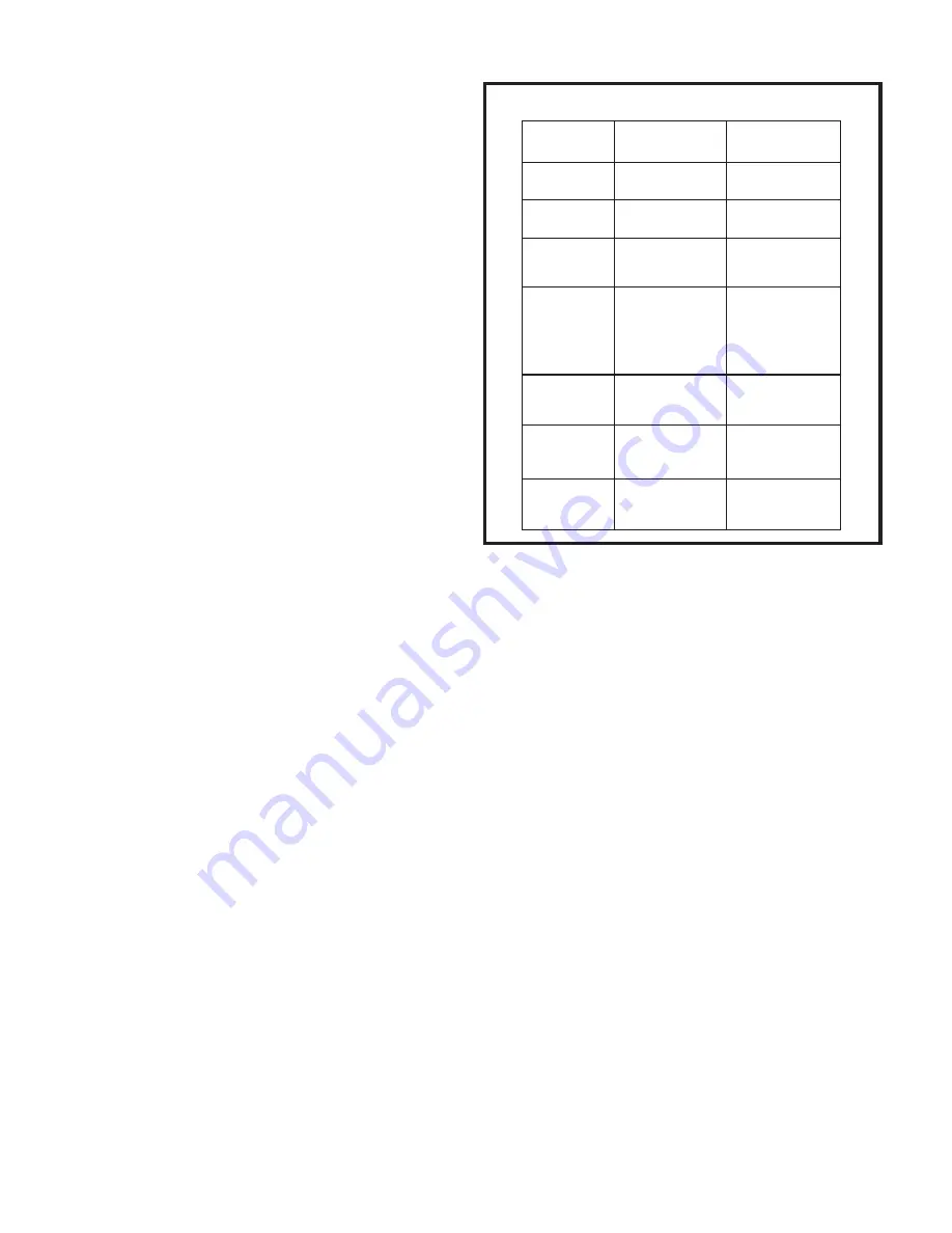
CONTROL SYSTEM DIAGNOSTICS
Fault Codes
Table 4
LED Status
Flashing Rate
Fault
Description
Slow Flash
Fast Flash
2 Flash
3 Flash
4 Flash
5 Flash
Steady
One flash
per second
Normal operaton:
No call for heat
Two flashes
per second
Normal operation:
Call for heat
Two flashes
in second with
1-second pause
Internal failure:
Micro-controller
failure; self-check
Five flashes in
2.5 seconds with
1-second pause
Flame sensed
and gas valve
not energized
Four flashes in
2 seconds with
1-second pause
High limit or
rollout switch
open
Three flashes in
1.5 seconds with
1-second pause
Pressure switch
senses incorrect
pressure or auxiliary
limit is open, or gas
valve coil is open.
System lockout:
Failed to detect
or sustain flame
--


