To reduce the risk of electric shock, fire, explosion, serious injury or death:
• Disconnect electric power to the dryer(s) before servicing.
• Close gas shut-off valve to gas dryer(s) before servicing.
• Never start the dryer(s) with any guards/panels removed.
• Whenever ground wires are removed during servicing, these ground wires must be reconnected
to ensure that the dryer is properly grounded.
WARNING
W001R1
70
505038
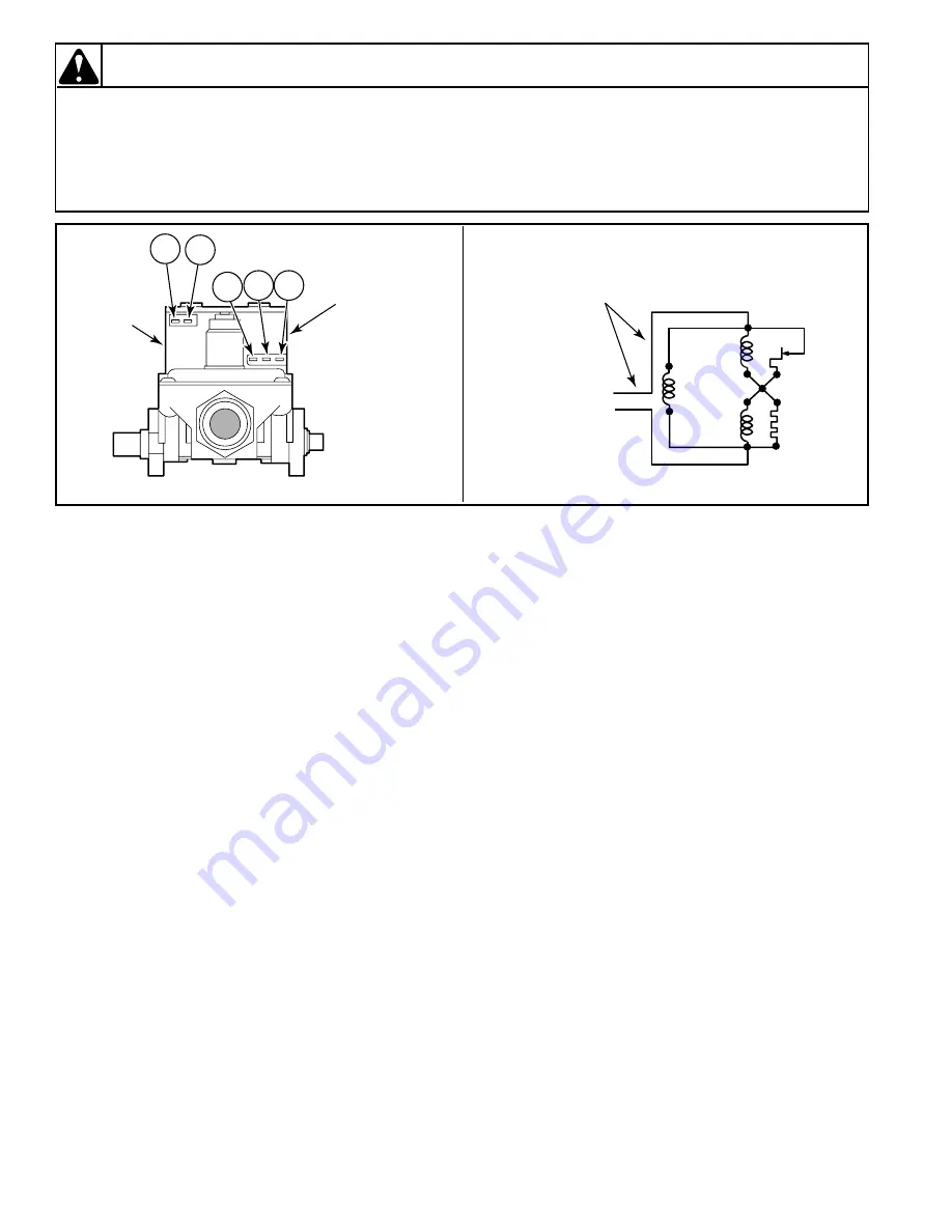
Figure 59
SECONDARY
COIL
HOLDING COIL
AND
BOOSTER COIL
(SPLIT COIL VALVE)
4
1
5
2
3
D267SE3B
SENSOR
SECONDARY
COIL
HOLDING
COIL
BOOSTER
COIL
IGNITER
120 VOLT, 60 HERTZ
ELECTRICAL
SUPPLY LINE
D268SE3A
56. BURNER SYSTEM OPERATION
(Gas Models – Figure 59)
a. Components
This burner has four basic components: a silicon
carbide (glow bar) igniter, burner tube, flame
sensor, and a two-stage gas valve consisting of a
split-coil valve and a secondary coil valve. The
split-coil valve is opened when the dryer
thermostat calls for heat, while the secondary
valve does not open until the igniter has attained
ignition temperature.
b. Pre-Ignition Circuits
When the dryer thermostat calls for heat, circuits
are completed through the holding coil, flame
sensor, booster coil and igniter. Both coils must
be energized to open the split-coil valve. Once
opened, the holding coil can hold the valve open
without assistance from the booster coil. The
flame sensor triggers the current to travel around
the secondary coil and through the igniter,
causing the igniter to get hot.
c. Burner Circuit
In approximately 30 seconds, the igniter attains
ignition temperature and ignition is made. The
heat from the burner flame causes the flame
sensor contacts (located on burner housing beside
the igniter) to open. A circuit is then completed
through the secondary valve coil, opening the
valve and allowing gas to flow.
d. Momentary Power Interruption
Upon resumption of power, flame sensor contacts
will still be open, permitting secondary valve to
open. However, with the secondary coil in the
circuit, the booster coil cannot draw enough
current to open the split-coil valve. When flame
sensor contacts do reclose, the secondary valve
will close, and the burner system will be in the
normal pre-ignition circuit.
e. Flame Failure
In case of flame failure, the flame sensor contacts
will re-close in about 45 seconds. This will close
the secondary valve and the burner system will
be in the normal pre-ignition circuit.
f. Ignition Failure
If flame is not established as flame sensor
contacts open, secondary valve will remain open
until flame sensor contacts re-close. Flame
sensor will continue to recycle the igniter and
secondary valve (about once per minute) until
ignition is made or dryer is turned off.


