


53273
19
Section 4 Service Procedures
To reduce the risk of electric shock, fire, explosion, serious injury or death:
• Disconnect electric power to the dryer(s) before servicing.
• Close gas shut-off valve to gas dryer(s) before servicing.
• Never start the dryer(s) with any guards/panels removed.
• Whenever ground wires are removed during servicing, these ground wires must be
reconnected to ensure that the dryer is properly grounded.
W001R1
WARNING
© Copyright, Alliance Laundry Systems LLC – DO NOT COPY or TRANSMIT
c. Nonmetered models with timer mounted on
control panel.
(1) Refer to Figure 2 for timer removal.
NOTE: Refer to appropriate wiring diagram when
rewiring timer.
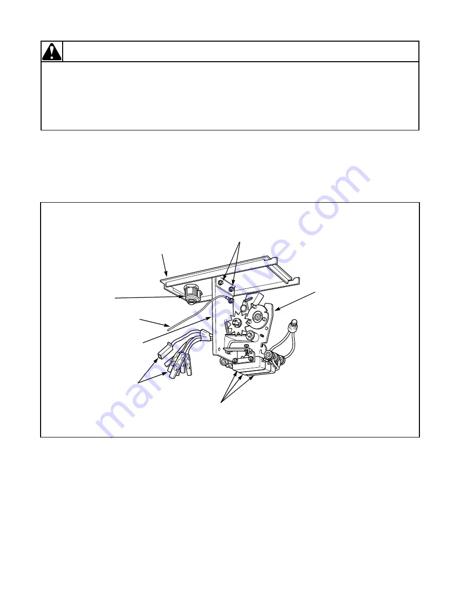
Figure 7
DRY958S
Service
Door
Bracket
Attaching Screws
Accumulator
Door
Lock
Ground
Wire
Bracket
Connectors
Switches


