18
Rockwell Automation Publication 7000-UM203C-EN-P - September 2018
Chapter 3
Operation, Installation, and Wiring
Wiring
Wiring to the safety components in the drive must be in accordance with the
following steps and must be carried out by competent personnel.
Important points to remember about control wiring:
• Always use tinned copper wire.
• Wire with an insulation rating of 600V or greater is recommended.
• Control wires should be separated from power wires by at least
0.3 meters (1 foot).
• Safety input wiring must be protected against external damage by cable
ducting, conduit, armored cable, or other means.
• Shielded cable is required.
• Refer to the Power and Control Wiring section of the applicable
PowerFlex 7000 User Manual.
Table 2 - Safe Torque Off Option Terminal Block Specifications
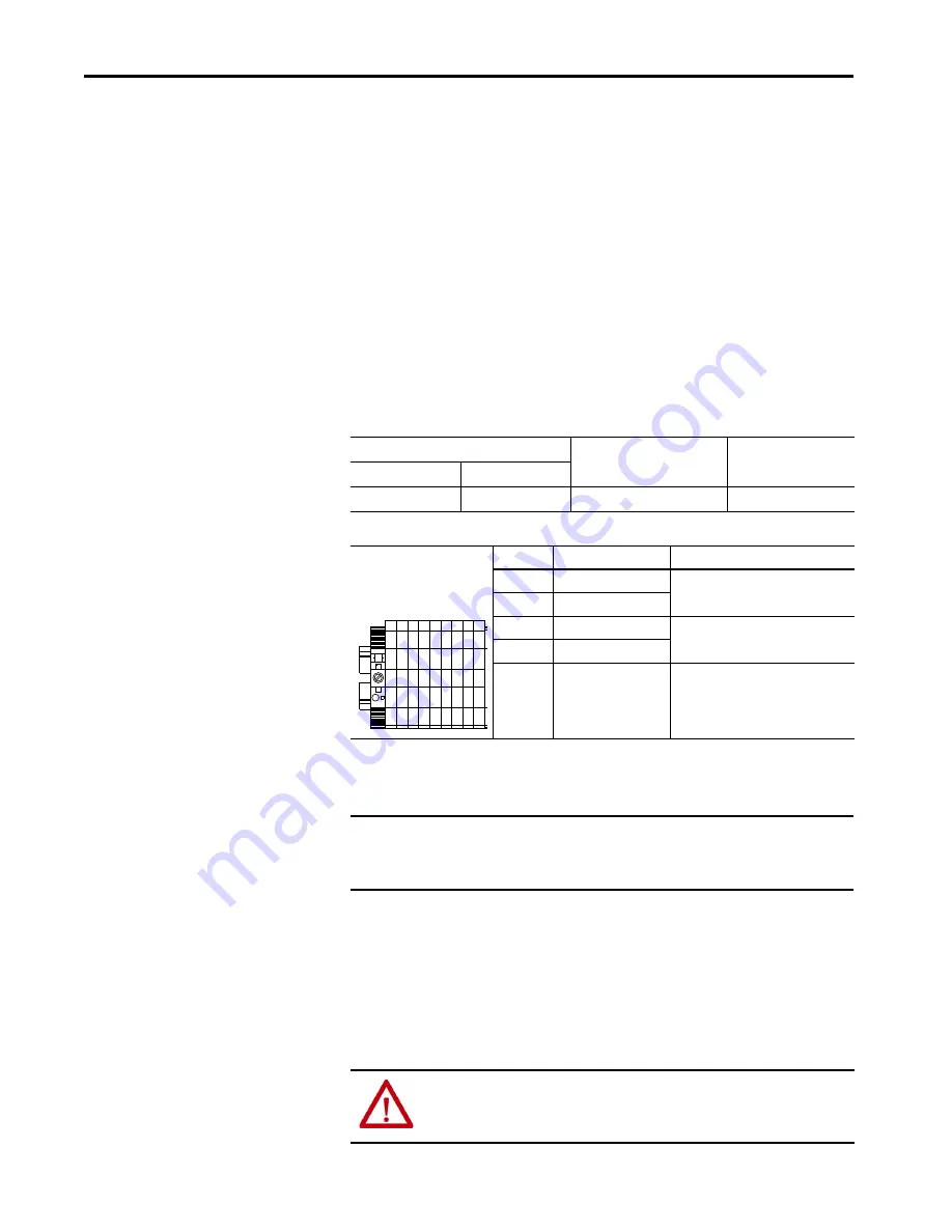
Table 3 - VFD6 Terminal Description
Drive Input Isolation Device
Interlock
The STO option requires both an interlock to open the drive input isolation
device and a feedback monitoring status to indicate the drive input isolation
device status.
Refer to the electrical drawings to show the proper interlocking based on the
type of input device used in the application. In all cases, the interlock connects
to the emergency stop input of the input device.
Wire Size Range
Wire Type
Strip Length
Maximum
Minimum
5.2 mm
2
(10 AWG)
0.3 mm
2
(22 AWG)
Single or Multi-conductor cable
10 mm (0.39 in.)
Terminal
Name
Description
D-1200
S12
Safety Input N.C. (Ch 1)
D-1201
S11 (via OIBBS)
D-1202
S22 (via OIBBS)
Safety Input N.C. (Ch 2)
D-1203
S21
D-1204
S34
Reset
D
-1
200
D
-1
201
D
-1
202
D
-1
203
D
-1
204
IMPORTANT
The term “Drive Input Isolation Device” refers to an electrically held
contactor or a circuit breaker with an undervoltage trip circuit used as the
drive input device.
ATTENTION:
Interlocking to a drive input isolation device must be done in
accordance with the recommendations in this manual and the system’s
electrical drawings.
Summary of Contents for PowerFlex 7000 Series
Page 41: ......


