Allen-Bradley 2755--SN5 Application Manual Download Page 211

11–11

Communicating with a PLC-5 Processor on a DeviceNet Network

Publication 2755-6.8

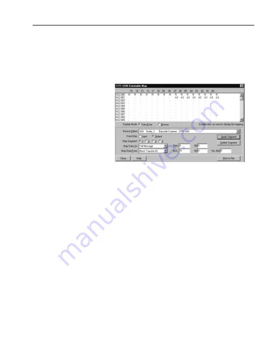
17. Next to Data Map, select Output to view the output file (N22).

The dialog shows the data table map for the N22 file.  The data
map represents data sent to the AdaptaScan Reader through the
SDN Scanner (BTW N22)

Word 1 writes one byte of data to the module.

Bit 7 of word 1 is the ‘send next message’ bit.

18. Change Map Data From to Poll Message.

19. Change Map Data To Block Transfer 62.

20. Change N22:0 to 1.

21. Change No. Bits to 8.

22. Click Apply Segment button.

23. Click Close to return the Scan List Editor dialog.

24. Click the Save To File button and then the Save to SDN button to

download the scan list the 1771-SDN Scanner.

Important:

Before clicking the Save to SDN button , the
SDN Scanner must be in Idle Mode.  Set bit 0 of
word 0 in the BTW N22 file to 0 (N22:0/0=0).
Another way to place the SDN Scanner in Idle
Mode is to put the PLC into Program Mode.

Summary of Contents for 2755--SN5

Page 1: ...Application Guide AdaptaScan Bar Code Readers Cat Nos 2755 SN3 SN5 and SN8 Allen Bradley...

Page 2: ...ifferences between solid state equipment and electromechanical devices that should be taken into consideration when applying products such as those described in this publication Reproduction of the co...

Page 3: ...the Discrete Input Module 1 6 Configure the Match Table 1 7 Configure a Package 1 8 Configure the Auto Load Trigger Source 1 9 Sending the Configuration to the Reader 1 10 Running the Application 1 1...

Page 4: ...Instances 3 10 Connecting the Computer to the RS 232 Port 3 10 Downloading Match Codes 3 11 Convert the Bar Code String to Hex 3 11 Place the String in the Data Packet 3 11 Send Data to the Reader 3 1...

Page 5: ...4 22 Viewing Match Code Downloads in Master Mode via Ladder Logic 4 25 Chapter 5 Overview 5 1 Hardware Requirements 5 1 Software Requirements 5 1 Related Publications 5 1 Connecting a BASIC Module to...

Page 6: ...twork 7 3 Connecting Readers to SLC 5 03 Controller 7 4 Connecting Readers to SLC 5 04 Controller 2 AIC Modules 7 5 Connecting Readers to SLC 5 04 Controller 1 AIC Module 7 6 Configuring the SLC Contr...

Page 7: ...e 8 10 Define the Message Format 8 11 Sending the Configuration to the Reader 8 12 Running the Application 8 12 Chapter 9 Overview 9 1 Hardware Requirements 9 1 Software Requirements 9 1 Related Publi...

Page 8: ...Scanner 10 8 Configuring the Reader 10 13 Create a New Project 10 13 Change the Baud Rate 10 14 Define the Bar Code Label 10 15 Define the DeviceNet Address 10 16 Configure the Scanner 10 16 Configur...

Page 9: ...dress 11 15 Configure the Scanner 11 15 Configure the Decoder Trigger 11 16 Create a Message 11 16 Define the Message Format 11 18 Sending the Configuration to the Reader 11 18 Running the Application...

Page 10: ...28 Downloading Other Host Commands 12 31 Chapter 13 Overview 13 1 Hardware Requirements 13 1 Software Requirements 13 1 Related Publications 13 2 PLC 5 Compatibility 13 2 Connecting the RB Module to...

Page 11: ...the Scanner 14 11 Configure the Decoder Trigger 14 12 Configure the Serial Port 14 12 Create a Message 14 14 Define the Message Format 14 15 Sending the Configuration to the Reader 14 15 Chapter 15 Ov...

Page 12: ...work 16 2 Connecting a Power Supply to a Reader 16 2 Multiple Reader Connections using Other Power Supply 16 3 Configuring Bar Code Reader 1 16 4 Create a New Project 16 4 Define the DeviceNet Address...

Page 13: ...Explicit Messaging 17 12 PanelView Tag Editor 17 14 Using the Electronic Data Sheet 17 17 Downloading Applications over a Serial Link 17 18 Downloading Application using the Internal DF1 Driver 17 18...

Page 14: ...mation the user of and those responsible for applying this information must satisfy themselves as to the acceptability of each application and use of the program In no event will Allen Bradley Company...

Page 15: ...BAS BASIC module 6 Communicating with an SLCt over an RS 232 Link Describes how to configure the reader to communicate with an SLC controller over an RS 232 serial connection 7 Communicating with an S...

Page 16: ...etwork Describes how to configure the reader to communicate with a 2760 RB module using DH 485 communication 15 Downloading Match Codes via DH485 using a PLC 5 Processor and a 2760 RB Module Describes...

Page 17: ...hway 485 Cable Installation Manual 1787 6 5 3 DeviceNet Manager Software Catalog No 1787 MGR User Manual 1749 6 5 5 DeviceNet Adapter Module Catalog No 1749 ADN User Manual 1747 6 5 2 DeviceNet Scanne...

Page 18: ...der 2755 NB40 or NB41 Wiring Base 2755 PW46 or PW47 Power Supply 2755 NC43 or NC48 Configuration Cable PHOTOSWITCH 42SRU 6203 2755 IB5S DC Input Module Computer running Windowst 3 1 or later or Window...

Page 19: ...No 2755 837 for more information regarding using an external power source External Input Contacts To 12V To To To GND 2755 IB5S The circuit must not draw more than 50mA from the Package Detect termina...

Page 20: ...ner configure the decoder trigger configure the discrete input module configure the match table package and autoload trigger source Create a New Project 1 Select New from the Project menu to create a...

Page 21: ...ode Labels dialog 2 Click the New button to add a label 3 Click the New button to add a symbol 4 Select the symbology and define attributes such as Identifier and Lengths 5 Click OK until you return t...

Page 22: ...ration Cable to the reader 4 Click the Apply button to send the DeviceNet address to the reader 5 Click Save and Close to return to the main Project dialog Configure the Scanner 1 Click the Scanner bu...

Page 23: ...le The application uses a discrete input module to trigger the Auto Load function The following procedure defines one of the two input output modules available in the AdaptaScan Bar Code Reader as an...

Page 24: ...e Match Table button on the main Project dialog 2 Click the New button to open the Match Function dialog 3 Select the following parameters for the Match Function Under Function select Auto Load Under...

Page 25: ...nstalled in wiring base when a No Match or No Read occurs The following procedure defines this package function 1 From the Match Table dialog click the Package button to open the Packages dialog 2 Cli...

Page 26: ...turn to the Match Table dialog Configure the Auto Load Trigger Source The application uses a discrete input module Discrete Input Output 2 to activate the Auto Load function The following procedure sh...

Page 27: ...symbol is scanned and decoded If the bar code data is unreadable or does not match the autoloaded match string I O LED 1 turns on The following illustration shows the auto load sequence using a Packa...

Page 28: ...r Code Reader The hardware items required for this application are 2755 SN3 SN5 or SN8 AdaptaScan Bar Code Reader 2755 NB40 or NB41 Wiring Base 2755 NC43 or NC48 Configuration Cable 2755 PW46 or PW47...

Page 29: ...232 port The other end of the cable is wired to the RS 232 port in the reader wiring base TX GND RX To Computer Wiring Base of Reader Use Belden 8303 or equivalent To Connector Compatible with Your C...

Page 30: ...nds to start stop scanning configure the serial port for terminal emulation define the format and content of messages Create a New Project Create a new project named ASCII Command Input for one Adapta...

Page 31: ...r Code Labels dialog 2 Click the New button to define a label 3 Click the New button to define a symbol for the label 4 Select the symbology and define attributes such as Identifier and Lengths 5 Clic...

Page 32: ...2755 NC43 or NC48 Configuration Cable to the reader 4 Click the Apply button 5 Click Save and Close to return to the Project dialog Configure the Scanner 1 Click the Scanner button on the Project dial...

Page 33: ...ct dialog 2 Under Triggered By select ASCII Command Input 1 from the Input list 3 Click the Save button 4 Click the Close button and return to the main Project dialog Configure the ASCII Commands The...

Page 34: ...haracter ASCII commands to trigger the decoder B Begin Scan E End Scan 4 In the Turn On field type the letter B The command is case sensitive 5 In the Turn Off field type the letter E If you do not us...

Page 35: ...the Maximum Length field type 1 With the Maximum Length set to 1 only one character is downloaded to the reader through the terminal via RS 232 port If a message is configured all bar code strings ar...

Page 36: ...ublication 2755 6 8 5 Click the Edit button under Protocol 6 Under Flow Control select None 7 Click OK to close the dialog 8 Click the Save button to save the serial configuration 9 Click Close to ret...

Page 37: ...om the main Project dialog 2 Under Triggered By check the Enable check box 3 Under Device select Bar Code Reader 1 4 Under Input select Decoder 5 Click the New button to define a message field 6 Under...

Page 38: ...essage Field dialog 12 Click OK to return to the Message dialog Define the Message Format This section defines the format of the message to display on the terminal emulator 1 Click the Format button f...

Page 39: ...owing illustration ASCII command B is entered to trigger the decoder to start scanning ASCII command E is entered to stop scanning A timeout occurs if an E is not entered Bar code data is displayed on...

Page 40: ...r PW47 Power Supply 2755 NC43 or NC48 Configuration Cable Communication Cable with Connector for PC Belden 8303 or equivalent Computer running Windows 3 1 or later or Windows 95 9 to 25 Pin Adapter fo...

Page 41: ...wiring base Tx GND RX To Computer Wiring Base of Reader Use Belden 8303 or equivalent To Connector Compatible with Your Computer RS 232 Port The following illustration shows how to connect a 2755 PW46...

Page 42: ...essage destination The steps may vary for some procedures because of the different requirements of applications For example the bar code labels may vary from one application to the next Create a New P...

Page 43: ...the Labels button to open the Bar Code Labels dialog 2 Click the New button to define a label 3 Click the New button to define Symbol 1 4 From the Symbology list box select I 2 of 5 To edit parameters...

Page 44: ...ct the 2755 NC43 or NC48 Configuration Cable to the Reader 4 Click the Apply button 5 Click the Close button and return to the Project dialog Configure the Scanner 1 Click the Scanner button on the Pr...

Page 45: ...r The Timer is typically used during initial setup to simulate a package detector The Timer is set for a specified On Time 1 second and Off Time 1 second 1 Click the Decoder button from the main Proje...

Page 46: ...Protocol check box Scanner Protocol is used when a host e g PLC or computer is connected to a serial port in the reader s wiring base 3 From the Connection list box select RS232 4 Click the Edit butt...

Page 47: ...he Match Table button on the main Project dialog 2 Click the New button to open the Match Function dialog 3 Under Function select Match Entry from the list box Match Entry specifies that a match occur...

Page 48: ...puts select Discrete Input Output 1 9 Click the Add button to add this selection to the Output To area 10 Click OK until you return to the Match Table dialog 11 Click Save and then Close to return to...

Page 49: ...The printout will show the class and instance numbers Disconnect the 2755 NC43 or NC48 Configuration Cable from the personal computer Connect the communication cable previously connected to the RS 23...

Page 50: ...aracters 04 were changed to 14 the hexadecimal value would be 0E This hexadecimal value is written as 0E00 Place the String in the Data Packet The bar code string is sent in a data packet having this...

Page 51: ...the Windows terminal function to send the data Locate the terminal icon usually within the Accessories group icon 2 Open the terminal icon 3 From the Settings menu open the Communications dialog and...

Page 52: ...0CE010003040030323030 The response of 3F90 indicates a good write of the match code 3F90 Address 3F 63 Response Code 90 Successful 94 Fail Note Refer to the next page for a description of the response...

Page 53: ...able 08 Service not supported 09 Invalid attribute value 0B Already in requested mode state 0C Object cannot perform service in its current mode state 0E Attribute not settable 0F Access permission do...

Page 54: ...eviceNet Address 3F DeviceNet Address 3F Set Attribute Request 10 Set Attribute Response 90 Class D2 Instance Number LSB 00 Instance Number MSB 00 Attribute Number Reset Counters 09 Data 01 3F Address...

Page 55: ...bute Request 0E Get Attribute Response 8E Class CC Data LSB 04 Instance Number LSB 00 Data MSB 00 Instance Number MSB 00 ASCII Message Data 30 Attribute Number Message 14 ASCII Message Data 32 3F Addr...

Page 56: ...09 Data LSB FA Data MSB 00 3F Address 63 modify as required Time in milliseconds LED Status Response Data at Indicated Bit Address LED State Byte Bits LED Indicator 0 Off 1 Yellow 2 Green 3 Red 4 Not...

Page 57: ...mands and response codes The hardware items required for this application are 2755 SN3 SN5 or SN8 AdaptaScan Bar Code Reader 2755 PW46 or PW47 Power Supply 2755 NC43 or NC48 Configuration Cable 2755 N...

Page 58: ...und screw on the reader s wiring base V 24V Ground Screw on Wiring Base Reader 2755 PW46 Power Supply The wiring base of the AdaptaScan Reader has an RS 485 RS 422 terminal block for point to point or...

Page 59: ...LC In other words when setting up the AdaptaScan via DH 485 the first priority is to process bar code data instead of finding node gaps Connecting Readers to SLC 5 03 Controller You must use a link co...

Page 60: ...vices on a DH 485 network must be terminated The wiring base of the AdaptaScan Reader provides a termination switch SLC 5 04 Processor Term A B Com Shield Chassis Gnd 1747 PIC 1747 AIC Module Term A B...

Page 61: ...arallels two 4 pair jacks and one 4 pair modular plug This adapter eliminates the second 1747 AIC module shown in the previous SLC 5 04 network diagram The end devices on a DH 485 network must be term...

Page 62: ...of messages and the message destination The steps may vary for some procedures because of the different requirements of applications For example the bar code labels may vary from one application to th...

Page 63: ...an SLC 5 03 or SLC 5 04 Controller Publication 2755 6 8 Define the Bar Code Label 1 Click the Label button to open the Bar Code Labels dialog 2 Click the New button to add a label to open the Bar Code...

Page 64: ...Click OK to return to the main Project dialog Define the DeviceNet Address 1 Click the Device button to open the Device dialog 2 Select a DeviceNet address Note The DeviceNet address is not always the...

Page 65: ...imum scanner focus 3 Click the Close button and return to the Project dialog Configure the Decoder Trigger This application uses a Timer to trigger the reader s decoder The Timer is typically used dur...

Page 66: ...ort button from the Project dialog 2 Set the parameters as follows From the Protocol list box select DH 485 From the Baud Rate list box select 19 200 Click the Scanner Protocol button From the Connect...

Page 67: ...Click the Protocol Edit button in the Serial Port dialog 2 Edit the parameters as follows Click the PCCC Enabled box From the Master Slave box select Slave From the Node box select 2 This is the DH48...

Page 68: ...he N9 Offset box select 100 which is the default This is the SLC destination address where the decoded bar codes are sent N9 is reserved for communications Bar code data is sent as an ASCII string to...

Page 69: ...ton to open the Match Function dialog and create a Match Function 3 Under Function select Match Entry Match Entry specifies that a match occurs whenever decoded bar code data matches the Rule entry 4...

Page 70: ...ct Discrete Input Output 1 9 Click the Add button to add this selection to the Output To area 10 Click OK to return to the main Match Table dialog Configure for a Package 1 Click the Package button to...

Page 71: ...to the main Package dialog Configure for an Output 1 Click the Output To button to specify which output activates when a No Read or No Match occurs 2 Under available Outputs select Discrete Input Outp...

Page 72: ...ton to download the configuration to the bar code reader When you download match codes from a host you need the instance number of the match table Do not assume that Match 1 Instance 1 Match 2 Instanc...

Page 73: ...ue shown above if the number of characters 04 were changed to 14 the hexadecimal value would be 0E This hexadecimal value is written as 0E00 Place the String in the Data Packet The bar code string is...

Page 74: ...to the next page for a description of the response code format and codes You can verify whether or not a correct match code was downloaded by placing a bar code label in front of the reader so that i...

Page 75: ...02 Resource unavailable 08 Service not supported 09 Invalid attribute value 0B Already in requested mode state 0C Object cannot perform service in its current mode state 0E Attribute not settable 0F...

Page 76: ...twork For complete details on configuring the SLC 5 04 or 5 03 processors refer to the Advanced Programming Software manuals SLC 5 04 Configuration 1 Establish communication with the Channel 0 port of...

Page 77: ...ED s will indicate a good match or a No Read or No Match MSG Read Write Read Write Type Target Device Local Remote Control Block Control Block Length WRITE PEER TO PEER 485CIF LOCAL N7 200 14 Message...

Page 78: ...s on the top of the reader When the downloaded match code matches a scanned label the Output 1 will turn on otherwise Output 2 will turn on for no read or no match Viewing Match Code Downloads in Sla...

Page 79: ...l Block An offset greater than 255 tells the MSG instruction that the SLC controller is talking to a bar code device Message Length in Elements 10 Message Timeout seconds 10 For the second Message Ins...

Page 80: ...Hex command 3F10CE010003040030333030 Byte Location 0 1 2 3 4 5 Byte Swapped N7 90 103F 01CE 0300 0004 3330 3030 In Slave Mode file N7 80 will contain the response for a successful download i e 3F90 o...

Page 81: ...O PEER 485CIF LOCAL N7 100 14 B3 0 Message Instruction Configuration Parameter Configuration Type Peer to Peer Read Write Write Target Device 485CIF Local Remote Local Control Block N7 100 Channel 0 T...

Page 82: ...Master Mode the N9 offset file will contain the response for a successful download i e 3F90 or failure i e 3F94 The offset address such as N9 100 is configured in the AdaptaScan OLP software DH485 dia...

Page 83: ...0 or NB41 Wiring Base 2755 PW46 or PW47 Power Supply 2755 NC43 or NC48 Configuration Cable 1746 SLC 500 Processor 1747 chassis 1746 power supply 1746 BAS BASIC module 1746 PIC RS 232 DH 485 convertor...

Page 84: ...st slot in a 1747 chassis Power is supplied externally to the 1747 chassis AdaptaScan Reader BASIC Module User Port 2 AdaptaScan Wiring Base RS232 Terminal Strip GND 5 2 TX RX 3 PIN PIN RS 232 Cable P...

Page 85: ...dshake bit O 1 0 8 once the data has been copied out of the M1 file Setting the bit triggers the BASIC module to turn off bit I 1 0 8 The first word of the M1 file contains the byte count and this wor...

Page 86: ...E 55 PUSH 0 REM STRING NUMBER NOT USED 60 PUSH 1 REM BYTE SWAPPING ENABLED 70 CALL 22 REM IMPLEMENT CALL STATEMENT 80 POP X REM STATUS OF CALL 22 INSTRUCTION 90 END 4 Press F1 to save the program 5 Pr...

Page 87: ...ATUS OF CALL 22 INSTRUCTION 90 END Make sure that the serial port of the BASIC module is set up the same as the AdaptaScan serial port This section shows how to configure the AdaptaScan Reader using t...

Page 88: ...h a 1746 BAS BASIC Module Publication 2755 6 8 3 Choose Edit from the Project menu to rename the project 1746 BASIC Module 4 Click Save to save the project under the new name and then Close to return...

Page 89: ...en the Bar Code Labels dialog 2 Click the New button to define a label 3 Click the New button to define a symbol for the label 4 Select the symbology and define attributes such as Identifier and Lengt...

Page 90: ...ce button to open the Device dialog 2 Select a DeviceNet address Note The DeviceNet address is not always the same as the DH 485 node address A DH 485 node address is assigned later 3 Connect the 2755...

Page 91: ...ation 2755 6 8 Configure the Scanner 1 Click the Scanner button on the Project dialog to open the Scanner dialog 2 Configure the scan pattern and use the Focus procedure for optimum scanner focus 3 Cl...

Page 92: ...sed during application setup Refer to Publication 2755 837 for other input sources that trigger the decoder 1 Click the Decoder button from the main Project dialog 2 Under Triggered By select Timer fr...

Page 93: ...and then Close to return to the main Project dialog Create a Message Data sent from the AdaptaScan Reader to the BASIC module uses messages 1 Click the Message button from the main Project dialog 2 U...

Page 94: ...when a no read occurs Note Enter 4 in the Length field of the Data Format The length parameter must be set to the number of characters in the bar code symbol The number 4 is chosen because a 4 charact...

Page 95: ...alog click the Send Device button to download the configuration to the bar code reader If the AdaptaScan Bar Code Reader is configured correctly and the BASIC module and SLC programs are entered as sh...

Page 96: ...Power Supply 2755 NC43 or NC48 Configuration Cable 1746 SLC 5 03 Enhanced Frn 6 0 or 5 04 Processor 1747 chassis 1746 power supply 1747 PIC module for communication between the processor and a persona...

Page 97: ...pply RS 232 Cable AdaptaScan Reader Host Port SLC 5 03 5 04 SLC 500 User Port 0 GND 5 3 TX RX 2 PIN PIN RS 232 Cable Pinouts AdaptaScan Wiring Base RS232 Terminal Strip The screens in this section sho...

Page 98: ...Feed LF These terminators along with the ARL instruction in the SLC 500 allow the User port to read in one message at a time with CR LF terminators The sample ladder logic below instructs the SLC 5 03...

Page 99: ...nner configure the decoder trigger configure the serial port configure the content and format of messages These procedures provide general guidelines for setting up an application You may need to modi...

Page 100: ...Project dialog Define the Bar Code Label 1 Click the Labels button to open the Bar Code Labels dialog 2 Click the New button to define a label 3 Click the New button to define a symbol for the label...

Page 101: ...2755 6 8 Define the DeviceNet Address 1 Click the Device button on the Project dialog 2 Set the DeviceNet address 3 Connect the 2755 NC43 or NC48 Configuration Cable to the reader 4 Click the Apply b...

Page 102: ...um scanner focus 3 Click the Close button and return to the Project dialog Configure the Decoder Trigger This application uses a Timer to trigger the reader s decoder The Timer is typically used durin...

Page 103: ...dialog 2 Verify that Terminal is selected in the Protocol list box Also verify that the settings match the Channel 0 User settings 3 Click the Edit button to open Terminal dialog 4 Set the attributes...

Page 104: ...ck the Message button from the main Project dialog 2 Under Triggered By check the Enable check box 3 Under Device select Bar Code Reader 1 4 Under Input select Decoder 5 Click the New button to define...

Page 105: ...urs 11 Click OK to return to the Message Field dialog 12 Click OK to return to the Message dialog Define the Message Format The format of the message is defined below 1 Click the Format button from th...

Page 106: ...figuration to the bar code reader Use the Monitor dialog to verify the decoding of bar code labels If the AdaptaScan Bar Code Reader is configured correctly and the SLC programs are entered as shown i...

Page 107: ...r code throughput as it is sent to the SLC The priority should be on processing bar code data not on finding node gaps The hardware items required for this application are 2755 SN3 SN5 or SN8 AdaptaSc...

Page 108: ...on 2755 6 8 Related publications include Publication Description 2755 837 AdaptaScan Bar Code Readers User Manual 2755 838 AdaptaScan Software User Manual In addition you may want to refer to the SLC...

Page 109: ...e AdaptaScan Reader has an RS 485 RS 422 terminal block for point to point or network connections This section shows three connection options Connecting readers to SLC 5 03 Connecting readers to SLC 5...

Page 110: ...point and network connections are the same The end devices on the DH 485 network must be terminated The wiring base of the AdaptaScan Reader provides a termination switch Termination Switch Ground Shi...

Page 111: ...ed The wiring base of the AdaptaScan Reader provides a termination switch SLC 5 04 Processor Term A B Com Shield Chassis Gnd 1747 PIC 1747 AIC Module Term A B Com Shield Chassis Gnd 1747 AIC Module 17...

Page 112: ...ne 4 pair modular plug This adapter eliminates the second 1747 AIC module shown on the previous page The end devices on a DH 485 network must be terminated The wiring base of the AdaptaScan Reader pro...

Page 113: ...nodes on the network For complete details on configuring the SLC 5 04 or 5 03 processors refer to the Advanced Programming Software manuals SLC 5 04 Configuration 1 Establish communication with the Ch...

Page 114: ...onfigure the decoder trigger configure the serial port configure the format of messages and the message destination The steps may vary for some procedures because of the different requirements of appl...

Page 115: ...to the Project dialog Define the Bar Code Label 1 Click the Labels button to open the Bar Code Labels dialog 2 Click the New button to define a label 3 Click the New button to define a symbol for the...

Page 116: ...tton on the Project dialog 2 Set the DeviceNet address to 1 Note The DeviceNet address is not always the same as the DH 485 node address A DH 485 node address is assigned later 3 Connect the 2755 NC43...

Page 117: ...ication 2755 6 8 Configure the Scanner 1 Click the Scanner button on the Project dialog to open the Scanner dialog 2 Configure the scan pattern and use the Focus procedure for optimum scanner focus 3...

Page 118: ...er 1 Click the Decoder button from the main Project dialog 2 Under Triggered By select Timer from the Input list 3 Click the Save button 4 Click the Close button and return to the main Project dialog...

Page 119: ...box select 3 This is the number of nodes on the network Under Destination select 1 from the Node list box This is the SLC node where the decoded bar codes are sent In the N9 Offset box type 100 which...

Page 120: ...1 Click the Message button from the main Project dialog 2 Under Triggered By check the Enable check box 3 Under Device select Bar Code Reader 1 4 Under Input select Decoder 5 Click the New button to...

Page 121: ...AD 1 to the controller when a no read occurs on Bar Code Reader 1 11 Click OK to return to the Message Field dialog 12 Click OK again to return to the Message dialog Define the Message Format 1 Click...

Page 122: ...to the Project From the Project dialog click the New button to add Bar Code Reader 2 to the project Define the DeviceNet Address 1 Click the Device button on the Project dialog 2 Set the DeviceNet ad...

Page 123: ...Bar Code Labels dialog 2 Click the New button to define a label 3 Click the New button to define a symbol for the label 4 Select a symbology and any other parameters Identifier Lengths required by you...

Page 124: ...Close button and return to the Project dialog Configure the Decoder Trigger This application uses a Timer to trigger the reader s decoder The Timer is typically used during application setup Refer to...

Page 125: ...ameters Edit the parameters as follows From the Node list box select 3 This is the node address of the reader on the network From the Maximum Node list box select 3 This is the number of nodes on the...

Page 126: ...ck the Enable box 3 Under Device select Bar Code Reader 1 4 Under Input select Decoder 5 Click the New button to create a message field 6 Under Symbol Source select Bar Code Reader 2 7 Under Bar Code...

Page 127: ...sage NO READ 2 when a no read occurs from Bar Code Reader 2 11 Click OK to return to the Message Field dialog 12 Click OK again to return to the Message dialog Define the Message Format 1 Click the Fo...

Page 128: ...Use the Monitor dialog to verify the decoding of bar code labels After downloading the configurations to both AdaptaScan Readers establish an online connection with the SLC processor Use the SLC data...

Page 129: ...ader 2755 NB40 or NB41 Wiring Base 2755 PW46 or PW47 Power Supply 2755 NC43 or NC48 Configuration Cable 1785 PLC 5 processor 1771 chassis 1771 power supply appropriate cables to program the PLC 5 and...

Page 130: ...lled in any acceptable slot in the 1771 chassis Channel 0 Bulletin 1771 Chassis PLC 5 Power Supply RS 232 or RS 422 AdaptaScan Reader RS232 Port Cabling RS 232 cabling must be constructed to connect t...

Page 131: ...ted PLC 5 30 40 60 Channel 0 2 TxD 14 TxD 3 RxD 16 RxD PIN Note Maximum run length 200 feet AdaptaScan Terminal Strip RS 422 485 RxA RxB TxA TxB PIN The screens in this section show the software confi...

Page 132: ...0xd or Carriage Return CR These terminators along with the ARL instruction in the PLC 5 allow the User port to read in one message at a time with CR LF terminators The sample ladder logic below instr...

Page 133: ...he scanner configure the decoder trigger configure the serial port configure the content and format of messages These procedures provide general guidelines for setting up an application You may need t...

Page 134: ...save the project under the new name and then Close to return to the Project dialog Define the Bar Code Label 1 Click the Labels button to open the Bar Code Labels dialog 2 Click the New button to defi...

Page 135: ...Labels dialog 6 Click Save and then Close to return to the Project dialog Define the DeviceNet Address 1 Click the Device button on the Project dialog 2 Set the DeviceNet address 3 Connect the 2755 N...

Page 136: ...s 3 Click the Close button and return to the Project dialog Configure the Decoder Trigger This application uses a Timer to trigger the reader s decoder The Timer is typically used during application s...

Page 137: ...erminal is selected in the Protocol list box Also verify that the settings match the Channel 0 User settings In this example RS232 is selected in the Connection list box 3 Click the Edit button to ope...

Page 138: ...eader when bar codes are decoded 1 Click the Message button from the main Project dialog 2 Under Triggered By check the Enable check box 3 Under Device select Bar Code Reader 1 4 Under Input select De...

Page 139: ...e characters no read when a no read occurs 11 Click OK to return to the Message Field dialog 12 Click OK to return to the Message dialog Define the Message Format The format of the message is defined...

Page 140: ...he configuration to the bar code reader Use the Monitor dialog to verify the decoding of bar code labels If the AdaptaScan Bar Code Reader is configured correctly and the PLC 5 program is entered as s...

Page 141: ...minal blocks one for upstream connection and one for downstream connection The hardware items required for this application are 2755 SN3 SN5 or SN8 AdaptaScan Bar Code Reader 2755 NB40 or NB41 Wiring...

Page 142: ...2 for more information regarding user termination information Computer 1770 KFD DeviceNet Interface Box AdaptaScan Bar Code Reader SLC 5 03 Processor 1747 SDN DeviceNet Scanner 1787 MGR DeviceNet Man...

Page 143: ...e bit to AdaptaScan Reader Message AddressingA Message Data is formatted the same as messages sent through the serial port When setting up the DeviceNet scanner for addressing message data use the fol...

Page 144: ...by changing the state of DeviceNet Output 16 of the DeviceNet I O A change of state 0 to 1 or 1 to 0 indicates that a new message is being sent Send Next Data Is indicated by changing the state of De...

Page 145: ...c program is for reference only Application specific interlocks may be necessary Rung 2 0 This rung enables Discrete Output bit 0 of slot 1 This will put the 1747 SDN card into run mode Remember in or...

Page 146: ...00 00 00 00 00 00 00 00 00 00 00 00 00 00 00 00 N23 60 00 00 00 00 00 00 00 00 00 00 00 00 00 00 00 00 00 00 00 00 N23 70 00 00 00 00 00 00 00 00 00 00 00 00 00 00 00 00 00 00 00 00 N23 80 00 00 00 0...

Page 147: ...0 O 1 7 00 00 O 1 8 00 00 O 1 9 00 00 O 1 10 00 00 O 1 11 00 00 O 1 12 00 00 O 1 13 00 00 O 1 14 00 00 O 1 15 00 00 Data Table File M1 Monitor Below is a partial listing of the M1 data table M1 1 1 co...

Page 148: ...work and apply DeviceNet Address 3 to the bar code reader See page 9 16 To configure the 1747 SDN DeviceNet Scanner 1 Double click the DeviceNet Manager icon 2 Create a new project with the network na...

Page 149: ...ers for the 1747 SDN Scanner If you are using an AdaptaScan with v7 0 firmware on a network with 2 or less nodes change the Interscan Delay parameter to 20 ms This will allow the AdaptaScan more CPU t...

Page 150: ...Net Network Publication 2755 6 8 6 Click the Edit I O Parameters button 7 Click the Polled button 8 Change the Poll Rx size to 8 9 Change the Poll Tx size to 1 10 Click the OK button to return to the...

Page 151: ...Map Data To M File 15 Change M1 1 to 1 16 Change No Bits to 64 17 Click Apply Segment The dialog shows the data table map of the SLC M1 file It displays data from the AdaptaScan Reader which is mappe...

Page 152: ...It displays data sent to the AdaptaScan Reader through the SDN Scanner N22 1 byte of data is written to the SDN Scanner Bit 7 of Word 1 is the send next message bit 24 Click the Close button to return...

Page 153: ...the decoder configure the format of messages and the message destination Create a New Project Create a new project named DeviceNet Master Slave for one AdaptaScan Bar Code Reader Bar Code Reader 1 1...

Page 154: ...eturn to the Project dialog Change the Baud Rate If you need to change the baud rate 1 Click on the K Baud button and select the desired baud rate 2 Click Save and Close to return to the Project dialo...

Page 155: ...n to define a label 3 Click the New button to define a symbol for the label 4 From the Symbology list select Interleaved 2 of 5 5 Under Lengths select the Length 1 check box and then type 4 in the Thr...

Page 156: ...ration Cable to the reader 4 Click the Apply button 5 Click Save and Close to return to the Project dialog Configure the Scanner 1 Click the Scanner button on the Project dialog to open the Scanner di...

Page 157: ...g 2 Under Triggered By select Timer from the Input list 3 Click the Save button 4 Click the Close button and return to the main Project dialog Create a Message Defines the content of messages sent fro...

Page 158: ...the Message Field Edit dialog 10 Under Replacement Strings type nr in the Fail field Bar code data is sent to the 1747 SDN Scanner on a valid read the Fail string sends the characters nr to the 1747...

Page 159: ...in Project dialog click the Send Device button to download the configuration to the bar code reader Note If you are using Send all to download multiple reader configurations unplug the DeviceNet scann...

Page 160: ...ext table provides troubleshooting information about the DeviceNet channel communication link If the NET indicator is this indicates Take this action Off the channel is disabled for DeviceNet communic...

Page 161: ...igure your module and change the addressing 78 slave device in scan list table does not exist node number alternately flashes Add the device to the network or delete the scan list entry for that devic...

Page 162: ...integrity Check system for failed slave devices or other possible sources of network interference 92 no network power detected on comm port Provide network power Make sure that module drop cable is pr...

Page 163: ...he DeviceNet network The wiring base has two DeviceNet terminal blocks one for upstream connection and one for downstream connection The hardware items required for this application are 2755 SN3 SN5 o...

Page 164: ...rmation regarding user termination information Computer 1770 KFD DeviceNet Interface Card AdaptaScan Bar Code Reader SLC 5 03 Processor 1747 SDN DeviceNet Scanner 1787 MGR DeviceNet Manager Software S...

Page 165: ...7 Send Message bit to AdaptaScan Reader Message AddressingB Message Data is formatted the same as messages sent through the serial port When setting up the DeviceNet scanner for addressing message dat...

Page 166: ...Is indicated by changing the state of DeviceNet Output 16 of the DeviceNet I O A change of state 0 to 1 or 1 to 0 indicates that a new message is being sent Send Next Data Is indicated by changing th...

Page 167: ...g ladder logic program is for reference only Application specific interlocks may be necessary Rung 2 0 This rung enables Discrete Output bit 0 of slot 1 This will put the 1747 SDN card into run mode R...

Page 168: ...0 00 00 00 00 00 00 00 00 00 00 00 00 00 00 00 00 00 00 00 00 N23 60 00 00 00 00 00 00 00 00 00 00 00 00 00 00 00 00 00 00 00 00 N23 70 00 00 00 00 00 00 00 00 00 00 00 00 00 00 00 00 00 00 00 00 N23...

Page 169: ...00 O 1 6 00 00 O 1 7 00 00 O 1 8 00 00 O 1 9 00 00 O 1 10 00 00 O 1 11 00 00 O 1 12 00 00 O 1 13 00 00 O 1 14 00 00 O 1 15 00 00 Data Table File M1 Monitor Below is a partial listing of the M1 data ta...

Page 170: ...eviceNet network and apply DeviceNet Address 3 to the bar code reader See page 10 16 To configure the 1747 SDN DeviceNet Scanner 1 Double click the DeviceNet Manager icon 2 Create a new project with t...

Page 171: ...n parameters for the 1747 SDN Scanner If you are using an AdaptaScan with v7 0 or lower firmware on a network with 2 or less nodes change the Interscan Delay parameter to 20 ms This will allow the Ada...

Page 172: ...using Explicit Messaging Publication 2755 6 8 6 Click the Edit I O Parameters button 7 Click the Polled button 8 Change the Poll Rx size to 8 9 Change the Poll Tx size to 1 10 Click the OK button to r...

Page 173: ...age 14 Change Map Data To M File 15 Change M1 1 to 1 16 Change No Bits to 64 17 Click Apply Segment The dialog shows the data table map of the SLC M1 file It displays data from the AdaptaScan Reader w...

Page 174: ...SLC M0 file It displays data sent to the AdaptaScan Reader through the SDN Scanner N22 1 byte of data is written to the SDN Scanner Bit 7 of Word 1 is the send next message bit 24 Click the Close but...

Page 175: ...re the scanner trigger the decoder configure the format of messages and the message destination Create a New Project Create a new project named SLC DeviceNet for one AdaptaScan Bar Code Reader Bar Cod...

Page 176: ...en Close to return to the Project dialog Change the Baud Rate If you need to change the baud rate 1 Click on the K Baud button and select the desired baud rate 2 Click Save and Close to return to the...

Page 177: ...the New button to define a label 3 Click the New button to define a symbol for the label 4 From the Symbology list select Interleaved 2 of 5 5 Under Lengths select the Length 1 check box and then type...

Page 178: ...viceNet address to 3 3 Connect the 2755 NC43 or NC48 Configuration Cable to the reader 4 Click the Apply button 5 Click Save and Close to return to the Project dialog Configure the Scanner 1 Click the...

Page 179: ...Project dialog 2 Under Triggered By select Timer from the Input list 3 Click the Save button 4 Click the Close button and return to the main Project dialog Create a Message Defines the content of mess...

Page 180: ...utton to open the Message Field Edit dialog 10 Under Replacement Strings type nr in the Fail field Bar code data is sent to the 1747 SDN Scanner on a valid read the Fail string sends the characters nr...

Page 181: ...he format and destination of messages sent from the reader 1 Click the Format button from the Message dialog 2 Under Message Destination select DeviceNet 3 Accept the defaults for all other parameters...

Page 182: ...button to open the Match Function dialog and create a Match Function 3 Under Function select Match Entry Match Entry specifies that a match occurs whenever decoded bar code data matches the Rule entry...

Page 183: ...ssaging Publication 2755 6 8 7 Click the Outputs button to specify which output activates when a match occurs 8 Under Available Outputs select Discrete Input Output 1 9 Click the Add button to add thi...

Page 184: ...lick the Package button to open the Package dialog 2 Click the new button to create a Package 3 Under Mode select No Read or No Match This mode is used to determine when a label is not read or does no...

Page 185: ...turn to the main Project dialog From the main Project dialog click the Send Device button to download the configuration to the bar code reader Use the Monitor dialog to verify the decoding of bar code...

Page 186: ...ssage Program Control only with devices that are slaves of your 1747 SDN Scanner Module These slave devices must be mapped in the scanner module s scan list Use the Explicit Message Program Control fe...

Page 187: ...ver to perform a function Response An explicit message sent by a server to a client in response to the client s request For every request issued there is a response 4 1305 AC drive 5 MC1 file transfer...

Page 188: ...224 word 225 word 226 Transaction Header 3 words word 255 15 0 One word two bytes 16 bits The transaction block is divided into two parts transaction header Contains information that identifies the t...

Page 189: ...to 255 The scanner uses this value to track the transaction to completion and returns the value with the response that matches the request downloaded by the processor The ladder logic program monitor...

Page 190: ...e processor and the scanner always originate in the processor The scanner module can only wait for the processor to download a transaction block to the module or request an upload of a transaction blo...

Page 191: ...st Transaction Block Response Transaction Block Ladder Scans Process Requests and Responses Request Transaction Blocks Response Transaction Blocks Scanner Response Queue Scanner Request Queue Execute...

Page 192: ...es in Request Transaction Blocks Service Name Service Code Example Get_Attribute_Single 0E hex Upload a single parameter value from a device Set_Attribute_Single 10 hex Download a single parameter val...

Page 193: ...N20 0 The DeviceNet address being written to in this example is 10 or 0AH Destination Source Length N25 0 M1 1 224 32 COP I 1 15 If bit 15 is enabled read the response data from the above command int...

Page 194: ...command sent from the SLC 5 03 you must 1 Send command down matchcode download TXID 11 2 Send a 03 in the status command Refer to page 10 26 for more information 3 Increment TXID to 12 4 Send command...

Page 195: ...tor NET The next table provides troubleshooting information about the DeviceNet channel communication link If the NET indicator is this indicates Take this action Off the channel is disabled for Devic...

Page 196: ...lashes Reconfigure your module and change the addressing 78 slave device in scan list table does not exist node number alternately flashes Add the device to the network or delete the scan list entry f...

Page 197: ...ysical media integrity Check system for failed slave devices or other possible sources of network interference 92 no network power detected on comm port Provide network power Make sure that module dro...

Page 198: ...cket Contents Response DeviceNet Address 3F DeviceNet Address 3F Set Attribute Request 10 Set Attribute Response 90 Class D2 Instance Number LSB 00 Instance Number MSB 00 Attribute Number Reset Counte...

Page 199: ...Net Address 3F Get Attribute Request 0E Get Attribute Response 8E Class CC Data LSB 04 Instance Number LSB 00 Data MSB 00 Instance Number MSB 00 ASCII Message Data 30 Attribute Number Message 14 ASCII...

Page 200: ...ttribute Number Max Time 09 Data LSB FA Data MSB 00 3F Address 63 modify as required Time in milliseconds LED Status Response Data at Indicated Bit Address LED State Byte Bits LED Indicator 0 Off 1 Ye...

Page 201: ...etwork The wiring base has two DeviceNet terminal blocks one for upstream connection and one for downstream connection The hardware items required for this application are 2755 SN3 SN5 or SN8 AdaptaSc...

Page 202: ...twork Computer 1770 KFD DeviceNet Interface Card AdaptaScan Bar Code Reader 1787 MGR DeviceNet Manager Software 6200 Series Programming Software 2755 ASN AdaptaScan Software Node 62 DeviceNet Trunk Ca...

Page 203: ...ord 1 Bit 7 Send Message bit to AdaptaScan Reader Message AddressingC Message Data is formatted the same as messages sent through the serial port When setting up the DeviceNet scanner for addressing m...

Page 204: ...y changing the state of DeviceNet Output 16 of the DeviceNet I O A change of state 0 to 1 or 1 to 0 indicates that a new message is being sent Send Next Data Is indicated by changing the state of Devi...

Page 205: ...n a DeviceNet Network Publication 2755 6 8 Note The following ladder logic program is for reference only Application specific interlocks may be necessary Note If you are using channel B instead of cha...

Page 206: ...0 00 00 00 N23 60 00 00 00 00 00 00 00 00 00 00 00 00 00 00 00 00 00 00 00 00 N23 70 00 00 00 00 00 00 00 00 00 00 00 00 00 00 00 00 00 00 00 00 N23 80 00 00 00 00 00 00 00 00 00 00 00 00 00 00 00 00...

Page 207: ...ply DeviceNet Address of 3 to the AdaptaScan Bar Code Reader See page 11 15 To configure the 1771 SDN DeviceNet Scanner 1 Double click the DeviceNet Manager icon 2 Create a new project with the networ...

Page 208: ...N22 0 instructions The SDN scanner maps data from the AdaptaScan Reader to its 62 word file This selection maps data to the N23 file in the PLC The BTW instruction writes data from the N22 file to the...

Page 209: ...ers dialog Under I O Type select the Polled check box In the Poll Rx Size box type 8 Bytes In the Poll Tx Size box type 1 Bytes From the Poll Rate list box select Every Scan The dialog should look lik...

Page 210: ...he N23 file The data from the AdaptaScan Reader is mapped to the PLC BTR N23 Word 0 is reserved 4 words 8 bytes are mapped for the incoming string from the AdaptaScan Reader Bit 15 is the new message...

Page 211: ...d next message bit 18 Change Map Data From to Poll Message 19 Change Map Data To Block Transfer 62 20 Change N22 0 to 1 21 Change No Bits to 8 22 Click Apply Segment button 23 Click Close to return th...

Page 212: ...e decoder trigger configure the format of messages and the message destination Create a New Project Create a new project named PLC DeviceNet for one AdaptaScan Bar Code Reader Bar Code Reader 1 1 Choo...

Page 213: ...urn to the Project dialog Change the Baud Rate If you need to change the baud rate 1 Click on the K Baud button and select the desired baud rate 2 Click Save and Close to return to the Project dialog...

Page 214: ...on to define a label 3 Click the New button to define a symbol for the label 4 From the Symbology list select Interleaved 2 of 5 5 Under Lengths select the Length 1 check box and then type 4 in the Th...

Page 215: ...to 3 3 Connect the 2755 NC43 or NC48 Configuration Cable to the reader 4 Click the Apply button 5 Click Save and Close to return to the Project dialog Configure the Scanner 1 Click the Scanner button...

Page 216: ...ain Project dialog 2 Under Triggered By select Timer from the Input list 3 Click the Save button 4 Click the Close button and return to the main Project dialog Create a Message This section defines th...

Page 217: ...to open the Message Field Edit dialog 10 Under Replacement Strings type nr in the Fail field Bar code data is sent to the 1771 SDN Scanner on a valid read the Fail string send the characters nr when a...

Page 218: ...he Message dialog 5 Click Save and then Close to return to the main Project dialog From the main Project dialog click the Send Device button to download the configuration to the bar code reader Use th...

Page 219: ...ing information about the Channel 1 and 2 communication links If the NET indicator is this indicates Take this action Off the channel is disabled for DeviceNet communication Power up the module provid...

Page 220: ...ntry node number alternately flashes Reconfigure your module for the correct transmit and receive data sizes 78 slave device in scan list table does not exist node number alternately flashes Add the d...

Page 221: ...m for failed slave devices or other possible sources of network interference 92 no network power detected on comm port Provide network power Make sure that module drop cable is providing network power...

Page 222: ...Reader to the DeviceNet network The wiring base has two DeviceNet terminal blocks one for upstream connection and one for downstream connection The hardware items required for this application are 275...

Page 223: ...ster slave network Computer 1770 KFD DeviceNet Interface Card AdaptaScan Bar Code Reader 1787 MGR DeviceNet Manager Software 6200 Series Programming Software 2755 ASN AdaptaScan Software Node 62 Devic...

Page 224: ...SDN Scanner Word 1 Bit 7 Send Message bit to AdaptaScan Reader Message AddressingD Message Data is formatted the same as messages sent through the serial port When setting up the DeviceNet scanner for...

Page 225: ...s indicated by changing the state of DeviceNet Output 16 of the DeviceNet I O A change of state 0 to 1 or 1 to 0 indicates that a new message is being sent Send Next Data Is indicated by changing the...

Page 226: ...Network using Explicit Messaging Publication 2755 6 8 Note The following ladder logic program is for reference only Application specific interlocks may be necessary Note If you are using channel B in...

Page 227: ...00 00 00 00 00 00 00 N23 60 00 00 00 00 00 00 00 00 00 00 00 00 00 00 00 00 00 00 00 00 N23 70 00 00 00 00 00 00 00 00 00 00 00 00 00 00 00 00 00 00 00 00 N23 80 00 00 00 00 00 00 00 00 00 00 00 00 0...

Page 228: ...etwork and apply DeviceNet Address of 3 to the AdaptaScan Bar Code Reader See page 12 15 To configure the 1771 SDN DeviceNet Scanner 1 Double click the DeviceNet Manager icon 2 Create a new project wi...

Page 229: ...k Transfer Write N22 0 instructions The SDN scanner maps data from the AdaptaScan Reader to its 62 word file This selection maps data to the N23 file in the PLC The BTW instruction writes data from th...

Page 230: ...e I O Parameters dialog Under I O Type select the Polled check box In the Poll Rx Size box type 8 Bytes In the Poll Tx Size box type 1 Bytes From the Poll Rate list box select Every Scan The dialog sh...

Page 231: ...able map of the N23 file The data from the AdaptaScan Reader is mapped to the PLC BTR N23 Word 0 is reserved 4 words 8 bytes are mapped for the incoming string from the AdaptaScan Reader Bit 15 is the...

Page 232: ...1 is the send next message bit 18 Change Map Data From to Poll Message 19 Change Map Data To Block Transfer 62 20 Change N22 0 to 1 21 Change No Bits to 8 22 Click Apply Segment button 23 Click Close...

Page 233: ...e decoder trigger configure the format of messages and the message destination Create a New Project Create a new project named PLC DeviceNet Master Slave for one AdaptaScan Bar Code Reader Bar Code Re...

Page 234: ...Close to return to the Project dialog Change the Baud Rate If you need to change the baud rate 1 Click on the K Baud button and select the desired baud rate 2 Click Save and Close to return to the Pr...

Page 235: ...the New button to define a label 3 Click the New button to define a symbol for the label 4 From the Symbology list select Interleaved 2 of 5 5 Under Lengths select the Length 1 check box and then typ...

Page 236: ...ceNet address to 3 3 Connect the 2755 NC43 or NC48 Configuration Cable to the reader 4 Click the Apply button 5 Click Save and Close to return to the Project dialog Configure the Scanner 1 Click the S...

Page 237: ...on from the main Project dialog 2 Under Triggered By select Timer from the Input list 3 Click the Save button 4 Click the Close button and return to the main Project dialog Create a Message This secti...

Page 238: ...Edit button to open the Message Field Edit dialog 10 Under Replacement Strings type nr in the Fail field Bar code data is sent to the 1771 SDN Scanner on a valid read the Fail string sends the charact...

Page 239: ...o return to the Message dialog 5 Click Save and then Close to return to the main Project dialog From the main Project dialog click the Send Device button to download the configuration to the bar code...

Page 240: ...Message Program Control only with devices that are slaves of your 1771 SDN Scanner Module These slave devices must be mapped in the scanner module s scan list Use the Explicit Message Program Control...

Page 241: ...ery request issued there is a response 4 1305 AC drive 5 Block Transfer Read file is completed TXID s are deleted and can be reused AdaptaScan Bar Code Reader 1 Format a Block Transfer Write file in t...

Page 242: ...nsaction Body 29 words word 0 word 1 word 2 Transaction Header 3 words word 31 15 0 One word two bytes 16 bits The transaction block is divided into two parts transaction header Contains information t...

Page 243: ...anner uses this value to track the transaction to completion and returns the value with the response that matches the request downloaded by the processor The ladder logic program monitors rollover and...

Page 244: ...words word 63 Transaction 2 Format of 64 word Block Transfer Read for Explicit Message Response How the Processor and Scanner Module Manage Messages Block transfer operations between the processor an...

Page 245: ...tches the responses to the requests using the TXID field Request Transaction Block Response Transaction Block Ladder Scans Process Requests and Responses Request Transaction Blocks Response Transactio...

Page 246: ...s Service Name Service Code Example Get_Attribute_Single 0E hex Upload a single parameter value from a device Set_Attribute_Single 10 hex Download a single parameter value to a device Get_Attribute_Al...

Page 247: ...file Length Continuous B3 2 ONS N7 200 N20 0 64 N B3 1 After BTW is complete initiate the the BTR statement to retrieve the response code The N7 inputs are needed if the code from page 12 5 is used N7...

Page 248: ...came from To receive the correct response from the command sent from the PLC 5 you must 1 Send command down matchcode download TXID 11 2 Send a 03 in the status command Refer to page 12 21 for more i...

Page 249: ...troubleshooting information about the Channel 1 and 2 communication links If the NET indicator is this indicates Take this action Off the channel is disabled for DeviceNet communication Power up the m...

Page 250: ...scan lists entry node number alternately flashes Reconfigure your module for the correct transmit and receive data sizes 78 slave device in scan list table does not exist node number alternately flas...

Page 251: ...Check system for failed slave devices or other possible sources of network interference 92 no network power detected on comm port Provide network power Make sure that module drop cable is providing n...

Page 252: ...et Contents Response DeviceNet Address 3F DeviceNet Address 3F Set Attribute Request 10 Set Attribute Response 90 Class D2 Instance Number LSB 00 Instance Number MSB 00 Attribute Number Reset Counters...

Page 253: ...t Address 3F Get Attribute Request 0E Get Attribute Response 8E Class CC Data LSB 04 Instance Number LSB 00 Data MSB 00 Instance Number MSB 00 ASCII Message Data 30 Attribute Number Message 14 ASCII M...

Page 254: ...ribute Number Max Time 09 Data LSB FA Data MSB 00 3F Address 63 modify as required Time in milliseconds LED Status Response Data at Indicated Bit Address LED State Byte Bits LED Indicator 0 Off 1 Yell...

Page 255: ...tems required for this application are 2755 SN3 SN5 or SN8 AdaptaScan Bar Code Reader 2755 NB40 or NB41 Wiring Base 2755 PW46 or PW47 Power Supply 2755 NC43 or NC48 Configuration Cable 2760 RB Interfa...

Page 256: ...5 type Use the following 2760 RB Interface Module type PLC 5 15 25 etc New Generation PLC 5 Series A Rev C or above Series A Rev G or below Refer to the sample PLC 5 Refer to the sample PLC 5 program...

Page 257: ...ced PLC 5 Processor DIP Switches witch Switch Lever Switch 1 2 3 4 5 6 7 8 9 10 SW 1 on on on on on on on on on off SW 2 on on on off off on on off on off I O Chassis Backplane DIP Switches Switch Lev...

Page 258: ...PLC For this application the AdaptaScan Reader communicates through port 1 on the 2760 RB A 1771 ASB module can also be used to communicate with the 2760 RB module over the chassis backplane to Remot...

Page 259: ...tion port Cable 2 must be constructed to connect the RS232 422 port of the bar code reader wiring base to Port 1 on the 2760 RB module Refer to following cabling diagrams 2760 RB config port Dumb Term...

Page 260: ...N7 5 Block Transfer Read O 13 15 15 Rack 0 Group 0 Module 0 Control Block N7 100 O Length 0 Continuous N Write Data N7 0 N7 5 Block Transfer Write 15 15 Rack 0 Group 0 O Module 0 Control Block N7 5 D...

Page 261: ...7 5 BT7 25 000 IIN BTR BRR BT7 5 BT7 25 Rack 0 EN EN Group 0 Module 0 O Control Block BT7 5 Data File N7 200 Length 0 O Continuous N Write BTW Data BT7 5 BT7 25 Rack 0 EN EN Group 0 Module 0 O Control...

Page 262: ...bits 1 stop bit no parity no flow control and either COM1 or COM2 depending on the smart cable connection B Program a function key to send the break sequence by using the Ctrl Shift Break command This...

Page 263: ...LE BYTE SWAPPING ENABLE DISABLE DISABLE BINARY DATA NO CONVERSIONS YES NO YES HDR TLR ON OUTPUT ENABLE DISABLE ENABLE HEADER BYTE LENGTH DEC 0 4 0 HEADER DATA 0 HEX 0 FF 0 HEADER DATA 1 HEX 0 FF 0 HEA...

Page 264: ...scanner configure the decoder trigger configure the serial port configure the content and format of messages These procedures provide general guidelines for setting up an application You may need to...

Page 265: ...n to the Project dialog Define the Bar Code Label 1 Click the Labels button to open the Bar Code Labels dialog 2 Click the New button to define a label 3 Click the New button to define a symbol for th...

Page 266: ...cation 2755 6 8 Define the DeviceNet Address 1 Click the Device button on the Project dialog 2 Set the DeviceNet address 3 Connect the 2755 NC43 or NC48 Configuration Cable to the reader 4 Click the A...

Page 267: ...optimum scanner focus 3 Click the Close button and return to the Project dialog Configure the Decoder Trigger This application uses a Timer to trigger the reader s decoder The Timer is typically used...

Page 268: ...roject dialog 2 Verify that Terminal is selected in the Protocol list box Also verify that the settings match the Channel 0 User settings 3 Click the Edit button to open Terminal dialog 4 Type r n in...

Page 269: ...ded 1 Click the Message button from the main Project dialog 2 Under Triggered By check the Enable check box 3 Under Device select Bar Code Reader 1 4 Under Input select Decoder 5 Click the New button...

Page 270: ...the characters no read when a no read occurs 11 Click OK to return to the Message Field dialog 12 Click OK to return to the Message dialog 13 Click Save and then Close to return to the main Project di...

Page 271: ...le 2760 RB Interface Module 1771 chassis PLC 5 processor 2760 SFC2 protocol cartridge appropriate cables to program the PLC 5 and to configure the 2760 RB module and bar code reader Computer running W...

Page 272: ...A Rev H or above Refer to the sample PLC 5 program on page 14 5 Refer to the sample PLC 5 program on page 14 6 Add ladder logic using IIN update of RB BTR must be before BTW The 2760 RB configuration...

Page 273: ...er Switch 1 2 3 4 5 6 7 8 SW 1 off off off off off off off off SW 2 off off off off off off off off SW 3 off off off off ot licable SW 4 off off on off Not Applicable The 2760 RB module is placed in t...

Page 274: ...ration port Cable 2 must be constructed to connect the RS485 port of the bar code reader wiring base to Port 1 on the 2760 RB module Refer to following cabling diagrams 2760 RB config port Dumb Termin...

Page 275: ...N7 5 Block Transfer Read O 13 15 15 Rack 0 Group 0 Module 0 Control Block N7 100 O Length 0 Continuous N Write Data N7 0 N7 5 Block Transfer Write 15 15 Rack 0 Group 0 O Module 0 Control Block N7 5 D...

Page 276: ...7 5 BT7 25 000 IIN BTR BRR BT7 5 BT7 25 Rack 0 EN EN Group 0 Module 0 O Control Block BT7 5 Data File N7 200 Length 0 O Continuous N Write BTW Data BT7 5 BT7 25 Rack 0 EN EN Group 0 Module 0 O Control...

Page 277: ...nu item 3 Device port protocol names Set to PORT1 COPYRIGHT 1989 ALLEN BRADLEY COMPANY INC 2760 SFC2 LAN SERIES A REVISION B YES NO YES 5 Select menu item 21 Identification numbers Select RS485 LAN 27...

Page 278: ...symbol configure the scanner configure the decoder trigger configure the serial port configure the format of messages and the message destination The steps may vary for some procedures because of the...

Page 279: ...n to the Project dialog Define the Bar Code Label 1 Click the Labels button to open the Bar Code Labels dialog 2 Click the New button to define a label 3 Click the New button to define a symbol for th...

Page 280: ...ce button on the Project dialog 2 Set the DeviceNet address to 1 Note The DeviceNet address is not always the same as the DH 485 node address A DH 485 node address is assigned later 3 Connect the 2755...

Page 281: ...Publication 2755 6 8 Configure the Scanner 1 Click the Scanner button on the Project dialog to open the Scanner dialog 2 Configure the scan pattern and use the Focus procedure for optimum scanner foc...

Page 282: ...decoder 1 Click the Decoder button from the main Project dialog 2 Under Triggered By select Timer from the Input list 3 Click the Save button 4 Click the Close button and return to the main Project di...

Page 283: ...under Protocol to edit the DH 485 parameters Edit the parameters as follows Select Slave under Master Slave From the Node list box select 1 This is the node address of the reader on the network 4 Cli...

Page 284: ...ges 1 Click the Message button from the main Project dialog 2 Under Triggered By check the Enable check box 3 Under Device select Bar Code Reader 1 4 Under Input select Decoder 5 Click the New button...

Page 285: ...rn to the Message Field dialog 12 Click OK again to return to the Message dialog Define the Message Format 1 Click the Format button from the Message dialog 2 In the Trailer text box type r n for CR L...

Page 286: ...PW47 Power Supply 2755 NC43 or NC48 Configuration Cable 2760 RB Interface Module 1771 chassis PLC 5 processor 2760 SFC2 protocol cartridge appropriate cables to program the PLC 5 and to configure the...

Page 287: ...compatibility bit S26 4 while in program mode Series A Rev H or above Refer to the sample PLC 5 program on page 15 5 Refer to the sample PLC 5 program on page 15 6 Add ladder logic using IIN update o...

Page 288: ...Switch Lever Switch 1 2 3 4 5 6 7 8 SW 1 off off off off off off off off SW 2 off off off off off off off off SW 3 off off off off ot licable SW 4 off off on off Not Applicable The 2760 RB module is...

Page 289: ...ule Configuration port Cable 2 must be constructed to connect the RS485 port of the bar code reader wiring base to Port 1 on the 2760 RB module Refer to following cabling diagrams 2760 RB config port...

Page 290: ...I 000 N7 0 N7 5 Block Transfer Read O 13 15 15 Rack 0 Group 0 Module 0 Control Block N7 100 O Length 0 Continuous N Write Data N7 0 N7 5 Block Transfer Write 15 15 Rack 0 Group 0 O Module 0 Control B...

Page 291: ...ssor BRR BT7 5 BT7 25 000 IIN BTR BRR BT7 5 BT7 25 Rack 0 EN EN Group 0 Module 0 O Control Block BT7 5 Data File N7 200 Length 0 O Continuous N Write BTW Data BT7 5 BT7 25 Rack 0 EN EN Group 0 Module...

Page 292: ...4 Select menu item 3 Device port protocol names Set to PORT1 COPYRIGHT 1989 ALLEN BRADLEY COMPANY INC 2760 SFC2 LAN SERIES A REVISION B YES NO YES 5 Select menu item 21 Identification numbers Select R...

Page 293: ...and symbol configure the scanner configure the decoder trigger configure the serial port configure the format of messages and the message destination The steps may vary for some procedures because of...

Page 294: ...hen Close to return to the Project dialog Define the Bar Code Label 1 Click the Labels button to open the Bar Code Labels dialog 2 Click the New button to define a label 3 Click the New button to defi...

Page 295: ...he same as the DH 485 node address A DH 485 node address is assigned later 3 Connect the 2755 NC43 or NC48 Configuration Cable to the reader 4 Click the Apply button 5 Click Save and Close to return t...

Page 296: ...s decoder The Timer is typically used during application setup Refer to the AdaptaScan Bar Code Readers User Manual Publication No 2755 837 for other input sources that trigger the decoder 1 Click th...

Page 297: ...list box select DH 485 From the Baud Rate list box select 19 200 From the Connection list box select RS485 The configuration must match the host configuration 3 Click the Edit button under Protocol to...

Page 298: ...n to open the Match Function dialog and create a Match Function 3 Under Function select Match Entry Match Entry specifies that a match occurs whenever decoded bar code data matches the Rule entry 4 Un...

Page 299: ...to add this selection to the Output To area 10 Click OK to return to the main Match Table dialog Configure for a Package 1 Click the Package button to open the Package dialog 2 Click the new button to...

Page 300: ...lable Outputs select Discrete Input Output 2 3 Click the Add button to add this selection to the Output To area 4 Click OK to return to the main Match Table dialog 5 Click Save and Close to return to...

Page 301: ...e Protocol User s Manual Publication No 2760 822 for more information 1 05 01 LSAP equals 80 and DH485 Node equals 1 Refer to Bulletin 2760 RS 485 LAN Master Slave Protocol User s Manual Publication N...

Page 302: ...Number MSB 03 Attribute Number Rule 04 Length of String LSB 00 Length of String MSB 30 ASCII 0 33 ASCII 3 30 ASCII 0 30 ASCII 0 Note You can use the Windows calculator to convert decimal values to he...

Page 303: ...e Codes Response codes have the following format Byte Contents 0 1 2 3 Mac ID Address x General Error Code x Additional Code 94 Error Response General Error Codes Code hex Name 02 Resource unavailable...

Page 304: ...owered by its own power supply The hardware items required for this application are 2755 SN3 SN5 or SN8 AdaptaScan Bar Code Reader 2755 NB40 or NB41 Wiring Base 2755 PW46 or PW47 Power Supply if not p...

Page 305: ...viceNet RS 232 In the illustration the next page each reader is powered by a separate Catalog No 2755 PW46 or PW47 power supply The Catalog No 2755 PW46 is shown Do not connect power supplies in paral...

Page 306: ...nections using Other Power Supply Below all readers are powered by another power supply Use a linear unregulated power supply The supply must provide 14 watts of power to each reader Use a shielded ca...

Page 307: ...trigger configure the serial port configure the format of messages and the message destination The steps may vary for some procedures because of the different requirements of applications For example...

Page 308: ...Save to save the project under the new name and then Close to return to the Project dialog Define the DeviceNet Address 1 Select Bar Code Reader 1 from the Project dialog 2 Click the Device button on...

Page 309: ...Code Labels dialog 2 Click the New button to define a label 3 Click the New button to define Symbol 1 4 From the Symbology list box select UPC A To edit parameters of the selected symbology click the...

Page 310: ...e New button to define label 3 13 Click the New button to define Symbol 1 14 From the Symbology list box select Code 39 To edit parameters of the selected symbology click the Symbologies button Config...

Page 311: ...ick the Decoder button from the main Project dialog 2 Under Triggered By select Package Detect from the Input list 3 Click the Save button 4 Click the Close button and return to the main Project dialo...

Page 312: ...1 Click the Message button from the main Project dialog 2 Under Triggered By check the Enable check box 3 Under Device select Bar Code Reader 1 4 Under Input select Decoder 5 Click the New button to o...

Page 313: ...n a no read occurs on Bar Code Reader 1 11 Click OK to return to the Message Field dialog 12 Click OK again to return to the Message dialog Define the Message Format 1 Click the Format button from the...

Page 314: ...Bar Code Reader 2 in the Project From the Project dialog select Bar Code Reader 2 Define the DeviceNet Address 1 Click the Device button on the Project dialog 2 Set the DeviceNet address to 2 for the...

Page 315: ...focus 3 Click the Close button and return to the Project dialog Configure the Decoder Trigger Bar Code Reader 2 is triggered by its own package detect device Refer to Publication No 2755 837 for othe...

Page 316: ...he Message button from the main Project dialog 2 Under Triggered By check the Enable check box 3 Under Device select Bar Code Reader 1 4 Under Input select Decoder 5 Click the New button to create a m...

Page 317: ...ader 2 11 Click OK to return to the Message Field dialog 12 Click OK again to return to the Message dialog Define the Message Format 1 Click the Format button from the Message dialog 2 In the Trailer...

Page 318: ...Bar Code Reader 3 in the Project From the Project dialog select Bar Code Reader 3 Define the DeviceNet Address 1 Click the Device button on the Project dialog 2 Set the DeviceNet address to 3 for the...

Page 319: ...focus 3 Click the Close button and return to the Project dialog Configure the Decoder Trigger Bar Code Reader 3 is triggered by its own package detect device Refer to Publication No 2755 837 for othe...

Page 320: ...ick the Message button from the main Project dialog 2 Under Triggered By check the Enable check box 3 Under Device select Bar Code Reader 1 4 Under Input select Decoder 5 Click the New button to creat...

Page 321: ...Reader 3 11 Click OK to return to the Message Field dialog 12 Click OK again to return to the Message dialog Define the Message Format 1 Click the Format button from the Message dialog 2 In the Trail...

Page 322: ...tions to Bar Code Reader 1 Bar Code Reader 2 and Bar Code Reader 3 When the application is running bar code data is sent from the three bar code readers and to the host device When selected from the M...

Page 323: ...55 NC43 or NC48 Configuration Cable DeviceNet trunk cable 2711 K9C10 T9C10 K9A10 or T9A10 PanelView 900 terminal 1747 L532 L541 L542 or L543 SLC Processor or 1785 PLC 5 processor and appropriate chass...

Page 324: ...als The table below lists the DeviceNet versions of the PanelView terminals The differences in the terminals relate to display type monochrome or color operator input touch screen or keypad The Device...

Page 325: ...PanelView 900 PanelView 900 DeviceNet Port Serial Link RS 232 Port Computer for developing PanelView applications 2711 T9A10 T9C10 2711 K9A10 K9C10 PLC 5 Controller DeviceNet Scanner Module Catalog No...

Page 326: ...DeviceNet Cable 492 ft 150m 1485C P1A300 Important Refer to the DeviceNet Cable System Planning and Installation Manual Publication No 1485 6 7 1 for network layout and design information DeviceNet P...

Page 327: ...T9A10 K9C10 T9C10 PanelView 900 Terminal Catalog Number 2711 K9A10 K9C10 9 Pin to 25 Pin Adapter if required Available Cables 2711 NC13 5 m 16 4 ft 2711 NC14 10 m 32 7 ft 2706 NC13 3 m 10 ft 1 2 3 4 5...

Page 328: ...Opens the numeric entry scratchpad Enter the node address 0 63 of the PanelView terminal on the DeviceNet link and press the Enter key A node address change takes effect on reset Active Node Address...

Page 329: ...tween each full scan of the Explicit Client tags in the current screen context This value is originally set by the downloaded application file but may be changed by an operator When changed the new va...

Page 330: ...for a PanelView application from New Application dialog when creating a new application or Terminal Setup dialog when converting the application created for another terminal Any catalog number with 1...

Page 331: ...s 0 to 63 of the PanelView terminal on the DeviceNet link Baud Rate Select the baud rate of the DeviceNet link The available baud rates are 125 kbps 250 kbps 500 kbps 9 Under I O Scanner edit the foll...

Page 332: ...nt screen context Note Time delays of less than 500 msec should be carefully considered since the Explicit Client mode will generate low priority network messaging at this interval Bus off Interrupt S...

Page 333: ...and the first output instance are exchanged using DeviceNet s I O slave messages with a maximum of 64 input and 64 output words exchanged If additional instances are configured they can only be acces...

Page 334: ...ommunicating with the PanelView must have a sufficient number of available connections to support an Explicit message connection by the PanelView and any other connections required by the application...

Page 335: ...Device Scanner Assembly Instance 1 Assembly Instance 2 PanelView Explicit Server Message Tags Input Tag Input Tag Output Tag Output Tag Server Device Scanner PC etc PanelView Input Tag Explicit Client...

Page 336: ...s not display it the tag name must be unique within a project cannot begin with 0 9 hyphen or percent tag names are not case sensitive do not use blanks tabs carriage returns non printable characters...

Page 337: ...icit Client Message Only Loads information using the Electronic Data Sheet Refer to page 17 17 we recommend that you load parameter data from the data sheet for the peer device Otherwise enter the tag...

Page 338: ...use blanks tabs carriage returns non printable characters maximum precision is 6 places to the right of the decimal point for non floating point values if present a sign or for the number must be fir...

Page 339: ...e dialog To load parameter data from the EDS 1 Click the Load From EDS button to open the Open dialog eds devnet PV900 Photo RediSt Drive 2 Select the EDS file you want to read 3 After the file is loa...

Page 340: ...ng the Internal DF1 Driver Choose Download from the Application menu Select the Download parameters Application is validated and translated to a PVA file Terminal resets verifies and starts applicatio...

Page 341: ...Expected Discrete Tag The Data Type implies that the Tag Address should specify a bit number Tag Tag Name Expected Analog Tag The Data Type implies that the Tag Address should not specify a bit numbe...

Page 342: ...eyond the 64 word limit of the Assembly Instance Tag Tag Name The length of the data extends beyond the size of the packet Adjust Packet Bytes to at least Increase the Packet Bytes assigned to the tag...

Page 343: ...t Data Type does not match the PanelView Data Type chosen It is recommended that Floating Point is chosen Floating Point corresponds most closely to the parameter chosen The DeviceNet Data Type does n...

Page 344: ...it message connections to allow the PanelView to take one If the targeted device is not UCMM capable ensure that it is owned by a Master device scanner etc 4 A zero length I O message was received pla...

Page 345: ...nfiguration screen 10 Unsupported DeviceNet message received Should not occur under normal operating conditions Clear the message and if the problem reoccurs consult Allen Bradley 12 Invalid ASA Numbe...

Page 346: ...radley 18 CAN Chip Failed to initialize Should not occur under normal operating conditions Reset the terminal and if the problem reoccurs consult Allen Bradley 37 The channel size of a particular chan...

Page 347: ...e supplied with power In this application you can use the AdaptaScan power supply Catalog No 2755 PW46 The power supplies used with DeviceNet are sized to the number of devices and DeviceNet cable len...

Page 348: ...lowing shows how the PanelView screen appears in PanelBuilder Catalog No 2711 ND3 You will need to create this screen for your application In this application the PanelView terminal displays decoded b...

Page 349: ...d Width is set to 24 characters and is based on the expected maximum bar code data length in characters The tag name is Bar_Code_Data By selecting the Edit Tag option you can edit the tag data as show...

Page 350: ...lay six digits of the Package count value the package count from the AdaptaScan can be up to ten digits By selecting the Edit Tag option you can edit the tag data as shown below The data type is Unsig...

Page 351: ...sent by a push button object in PanelView The dialog box for the package count reset push button is shown below By selecting the Edit Tag option you can edit the tag data as shown below Note The Write...

Page 352: ...on No 2755 838 for information regarding the basic set up of the AdaptaScan Bar Code Reader The following sections only provide the information necessary to make the data available for the PanelView t...

Page 353: ...k Publication 2755 6 8 Making Package Counter Data Available Package counter data must be made available to the PanelView terminal by setting up an unconditional match in the AdaptaScan Bar Code Reade...

Page 354: ...Lebanon Macau Malaysia Malta Mexico Morocco The Netherlands New Zealand Nigeria Norway Oman Pakistan Panama Peru Philippines Poland Portugal Puerto Rico Qatar Romania Russia Saudi Arabia Singapore Slo...

Reviews: