


10–23
Communicating with an SLC 5/03 Processor on a DeviceNet Network using Explicit Messaging
Publication 2755-6.8
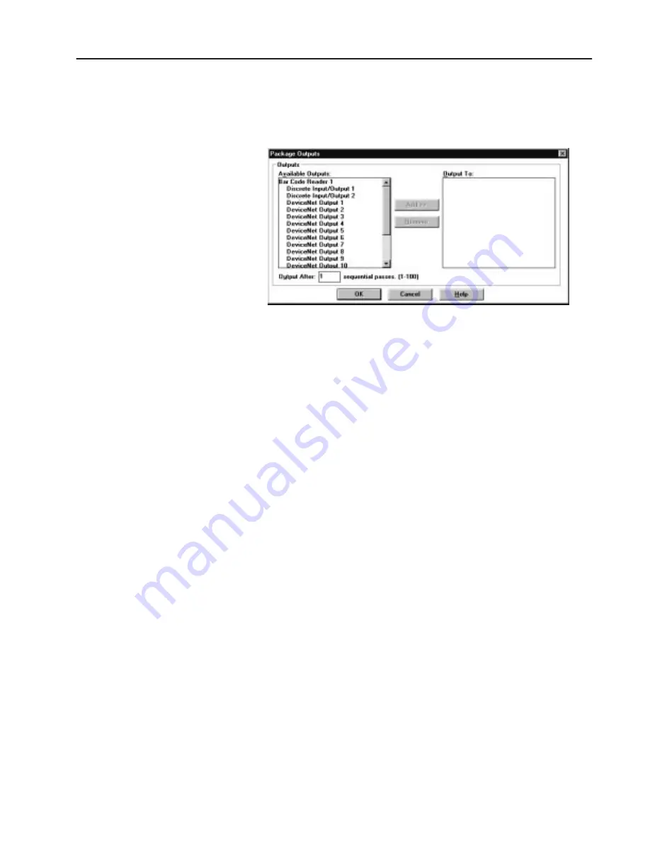
Configure for an Output
1. Click the Output To button to specify which output activates
when a No-Read or No-Match occurs.
2. Under available Outputs, select Discrete Input/Output 2.
3. Click the Add>> button to add this selection to the
Output To: area.
4. Click OK to return to the main Match Table dialog.
5. Click Save and Close to return to the main Project dialog.
From the main Project dialog, click the Send Device button to
download the configuration to the bar code reader.
Use the Monitor dialog to verify the decoding of bar code labels.
If the:
•
AdaptaScan Reader is configured correctly,
•
the 1747-SDN Scanner is configured correctly, and
•
the ladder program is entered as shown in this application,
you will see bar code data or ‘nr’ in the SLC M1 file (N23) as bar
code symbols are decoded. Remember that all data is byte swapped.
If the 1747-SDN Scanner is not working properly, refer to the
troubleshooting section.
Sending the Configuration
to the Reader
Running the Application


