Allen-Bradley 1734-SSI User Manual Download Page 21

Rockwell Automation Publication 1734-UM007E-EN-P - October 2015

21

Chapter

 3

Communicate with Your Module

About This Chapter

Read this chapter for information about how the 1734-SSI module transmits SSI 
sensor data over the DeviceNet network.

About Communications

Data can be exchanged with the master through a polled, cyclic, or change-of-
state connection. Bit-strobe Command Response Messaging and the 
Unconnected Message Manager (UCMM) are not supported.

(1)

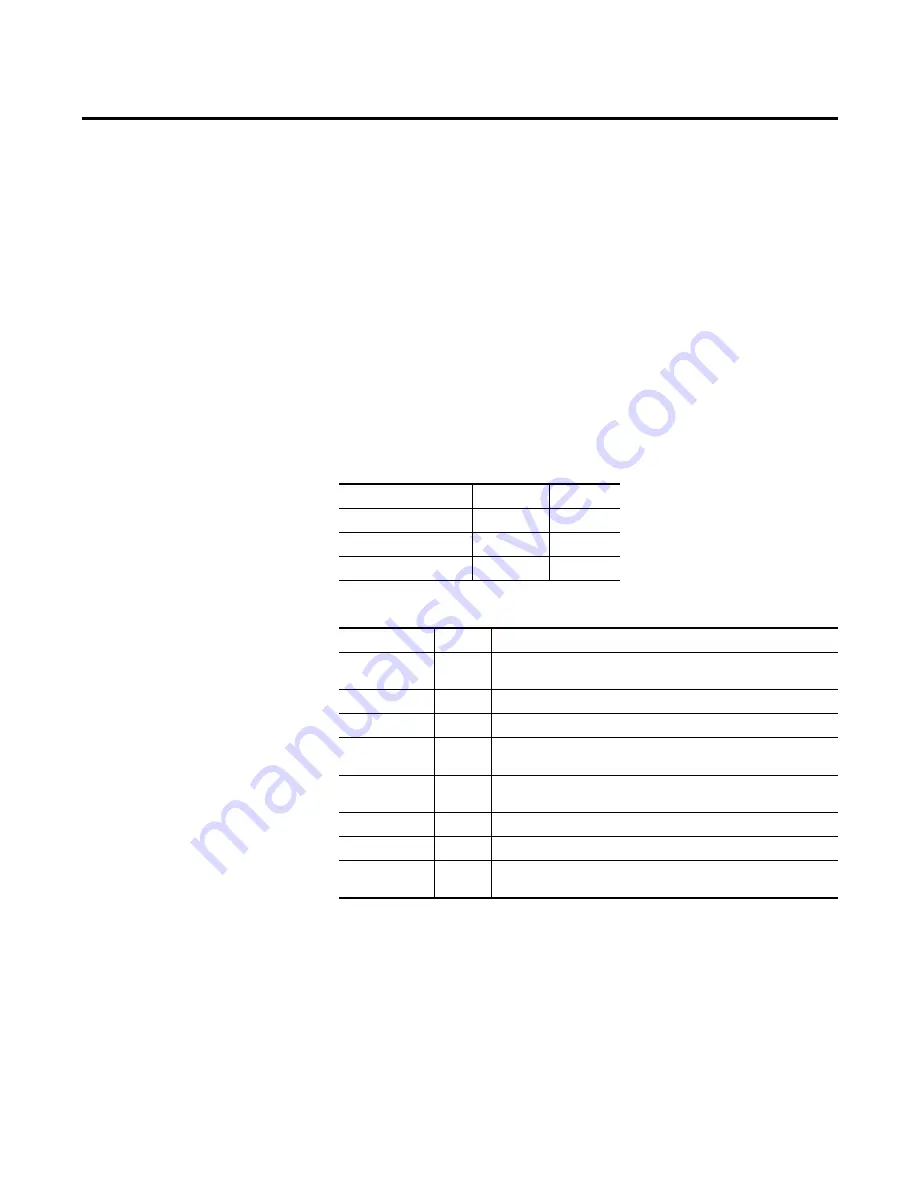
The module produces and consumes data as follows:

See the following tables for consume and produced bit and byte definitions.

(1) If you are not familiar with these terms, see the DeviceNet Specification for definitions (online: www.odva.org).

I/O Connection Type

Consumes

Produces

Polled

2 bytes

10 bytes

Cyclic

2 bytes

10 bytes

Change-of-state

2 bytes

10 bytes

Byte

Bit

Description

Produce 0

0...7

Low byte of present low SSI word. Bit 0 is the least significant bit of the entire 
present SSI word.

Produce 1

0...7

High byte of present low SSI word.

Produce 2

0...7

Low byte of present high SSI word.

Produce 3

0...7

High byte of present high SSI word. Bit 7 is the most significant bit of the entire 
present SSI word.

Produce 4

0...7

Low byte of latched low SSI word. Bit 0 is the least significant bit of the entire 
latched SSI word.

Produce 5

0...7

High byte of latched low SSI word.

Produce 6

0...7

Low byte of latched high SSI word.

Produce 7

0...7

High byte of latched high SSI word. Bit 7 is the most significant bit of the entire 
latched SSI word.

Summary of Contents for 1734-SSI

Page 1: ...POINT I O Synchronous Serial Interface Absolute Encoder Module Catalog Number 1734 SSI User Manual ...

Page 2: ...l in whole or in part without written permission of Rockwell Automation Inc is prohibited Throughout this manual when necessary we use notes to make you aware of safety considerations Labels may also be on or inside the equipment to provide specific precautions Allen Bradley Rockwell Software and Rockwell Automation are trademarks of Rockwell Automation Inc Trademarks not belonging to Rockwell Aut...

Page 3: ...al contains new and updated information Changes throughout this revision are marked by change bars as shown to the right of this paragraph New and Updated Information This table contains the changes made to this revision Topic Page Updated Parameters 12 13 and 14 in Parameter Object table 24 ...

Page 4: ...4 Rockwell Automation Publication1734 UM007E EN P October 2015 Summary of Changes Notes ...

Page 5: ... 15 Add the Adapter to Your Network 15 Add I O Modules to Your Network 16 Set the Encoder s Parameters 17 Check I O Status and View the EDS File 19 Chapter3 CommunicatewithYourModule About This Chapter 21 About Communications 21 Communicate Real time Information 22 Operating Modes 24 Chapter4 SetandOperateYourModule About This Chapter 27 Module Configuration Value Definitions 27 Operation of the D...

Page 6: ...esinRSLogix5000 Software About This Appendix 37 Understand Data Connection and Communication Formats 37 Configure Your Module 38 Use the Help Button 38 Work with the Feedback Dialog 39 Work with the Conversion Dialog 40 Work with the Input Registration Dialog 41 Work with the Watch Position Dialog 42 Index ...

Page 7: ...rning related products from Rockwell Automation For This Information See Install the Module Chapter 1 Configure the Module Chapter 2 Communicate with Your Module Chapter 3 Set and Operate Your Module Chapter 4 Diagnose Problems Chapter 5 Configure Modules in RSLogix 5000 software Appendix A Description Cat No Publication Analog Input Modules Installation Instructions 1734 IE2C 17340IE2V 1734 IN027...

Page 8: ...en Bradley distributor or Rockwell Automation sales representative Source Output Modules Installation Instructions 1734 IV2 1734 IV4 1734 IV8 1734 IN052 Very High speed Counter Modules Installation Instructions 1734 VHSC5 1734 VHSC24 1734 IN003 Wiring Base Assembly Installation Instructions 1734 TB 1734 TBS 1734 IN511 Wiring Base Assembly Installation Instructions 1734 TB3 1734 TB3S 1734 IN013 Des...

Page 9: ...le collects serial data from industrial absolute position encoding sensors that use a standard SSI protocol Description Description 1 Module locking mechanism 6 Slide in writable label 2 Module wiring diagram 7 Insertable I O module 3 DIN rail locking screw orange 8 Removable terminal block handle 4 Mechanical keying orange 9 Removable terminal block 5 Interlocking side pieces 10 Mounting base NOD...

Page 10: ...ting base To install the mounting base wiring base assembly on the DIN rail proceed as follows 1 Position the mounting base wiring base assembly vertically above the installed units adapter power supply or existing module 2 Slide the mounting base down allowing the interlocking side pieces to engage the adjacent module or adapter ATTENTION POINT I O is grounded through the DIN rail to chassis grou...

Page 11: ...all the module before or after base installation Make sure that the mounting base is correctly keyed before installing the module into the mounting base In addition make sure the mounting base locking screw is horizontal referenced to the base 1 Using a bladed screwdriver rotate the keyswitch on the mounting base clockwise till the number required for the type of module being installed aligns with...

Page 12: ...wiring To reinsert the removable terminal block proceed as follows 1 Insert the RTB end opposite the handle into the base unit The end has a curved section that engages with the mounting base 2 Rotate the terminal block into the mounting base until it locks itself in place NODE 1734 SSI WARNING When you connect or disconnect the removable terminal block RTB withfield sidepowerapplied anelectricala...

Page 13: ... 6 Use a small bladed screwdriver to rotate the orange DIN rail locking screw on the mounting base to a vertical position This releases the locking mechanism 7 Lift the mounting base straight up to remove WARNING When you connect or disconnect the removable terminal block RTB withfield sidepowerapplied anelectricalarccanoccur Thiscouldcause an explosion in hazardous location installations Be sure ...

Page 14: ...plosion in hazardous location installations Be sure that power is removed or the area is nonhazardous before proceeding Module Status Network Status 1734 SSI NODE RUN UP I1 DOWN COMP Module status Network status Run status Up status Down status Comp status D V Shield C D V I1 C D Data I1 Digital Sourcing Input 1 C Clock V SSI Sensor Module Terminations 0 D 1 1 D 1 2 V 3 V 4 Shield 5 I1 6 C 1 7 C 1...

Page 15: ...modes The primary difference is that if you make changes offline you must go online before the configuration changes take effect Add the Adapter to Your Network To add the adapter to your network follow these steps 1 Start the RSNetWorx for DeviceNet software 2 Add the communication device as shown noting that in this case the chosen device was a 1734 ADN DeviceNet adapter 1 Click the here to expa...

Page 16: ...gure The out of the box node setting for 1734 modules is 63 You can change the setting by using the node commissioning tool The node commissioning tool is available either online or offline 2 Double click the module to change the node address 1 Click the here to expand the list of specialty modules 2 Double click the catalog number to choose the module You can also click and drag the module name o...

Page 17: ... shown in the figure You see a dialog with a series of tabs Each tab provides options to view or edit IMPORTANT Thischaptershowsconfigurationintheonlinemode Changessetinthismode take effect when you download to the individual module 1 Click the module to highlight it 2 From the Device menu choose Properties You can also right clickthemoduleorname andthe property dialog pops up These are the tabs y...

Page 18: ...odule s device identity These fields are read only Click the Device parameters tab to get to the dialog for setting the parameters At any point you can click here to finish changing configuration parameters If configuration changes are made in offline mode they do not take effect until the system goes online This dialog appears after you click the Device parameters tab If you want the existing par...

Page 19: ...ts setup and the EDS file by clicking the appropriate tab To configure your module select Configuration and modify the parameters as desired for your application Click OK when finished Click the I O Data tab to display the default characteristics for this module Thisdialogshowstheinput output defaults for the three modes These are Polled Change of state Cyclic ...

Page 20: ...007E EN P October 2015 Chapter 2 Configure the Module Click the EDS File tab to display the statistics of the EDS file used to configure this module Click View File to view the actual EDS file You can view the actual EDS file or edit the file ...

Page 21: ... Specification for definitions online www odva org I O Connection Type Consumes Produces Polled 2 bytes 10 bytes Cyclic 2 bytes 10 bytes Change of state 2 bytes 10 bytes Byte Bit Description Produce 0 0 7 Low byte of present low SSI word Bit 0 is the least significant bit of the entire present SSI word Produce 1 0 7 High byte of present low SSI word Produce 2 0 7 Low byte of present high SSI word ...

Page 22: ... RES RES RES RES RES RES RES 1 Monitor IDF to determine the validity of the produced data If IDF 1 the SSI data is false 2 The master must provide the Master ACK Byte in order to receive the polled Produced bytes 0 9 I1 Input 1 Status 1 Input 1 ON 0 OFF RUN SSI Clock Output Status 1 Clock Output ON 0 OFF DEC SSI Data Count Decreasing 1 Decreasing 0 Not Decreasing INC SSI Data Count Increasing 1 In...

Page 23: ...ay to Binary Conversion 1 Standardization 1 SSI Word Delay Time 2 Trailing Bits 1 Latch Input Control 1 Sensor Resolution 2 Sensor Cycles 2 Alignment Byte 0x00 2 Comparator 1 Value 4 Comparator 2 Value 4 Comp 1 Control 1 Comp 2 Control 1 Firmware Version 4 001 and above 123 0x7B Set Get Run 1 Gray Binary 1 SSI Word Length 1 Data Rate 1 Gray to Binary Conversion 1 Standardization 1 SSI Word Delay T...

Page 24: ...r 2 Value 4 19 SSI Word Filter Control 1 1 This parameter is present in firmware version 4 001 and later 1 Parameter Value 1 Notes Run Enable Disable Turns SSI data clock on or off Data Type Binary or Gray SSI sensor s data type Data Word Length 2 31 13 Length of the received serial data word can be any size between 2 and 31 data bits Bit 32 is used forLatch Input detection Data Rate 125 250 500K ...

Page 25: ...utions for a rotary encoder strokes for a linear displacement transducer Latch Input Off Rising Edge Falling Edge Both Edges Master unlatches data by transmitting the LACK bit over the network Comparator 1 Not Active Up Direction Down Direction Both Directions Module compares data to value from the master Only one Compare value can be active Comparator 2 Not Active Up Direction Down Direction Both...

Page 26: ...26 Rockwell Automation Publication1734 UM007E EN P October 2015 Chapter 3 Communicate with Your Module Notes ...

Page 27: ... that other module features operate correctly SSI Word Length The number of bits in a single SSI word is completely determined by the SSI sensor See the manufacturer s data sheet for the sensor output word size The word length setting range is 2 31 bits The default SSI word length is 13 bits Data Rate The data rate is the SSI sensor s communication rate bits s stated in the manufacturer s data she...

Page 28: ... steps per revolution for a rotary sensor or total number of steps per stroke for a linear or optical transducer The Sensor Resolution value is not used by the module and is not needed for proper module operation with your SSI sensor The Sensor Resolution value can be passed to the network master for processing if desired The range is 1 65 535 steps and the default value is 1 Sensor Cycles The tot...

Page 29: ...OFF data latching simultaneously With one of the Latch Input modes active watch the module Status Word status bytes 0 and 1 for I1 input operation When I1 is ON bit I1 in Status Byte 0 bit 0 of Status Byte 0 is 1 If I1 is OFF the I1 bit is 0 When the I1 input is activated corresponding to the Latch Input mode the current SSI sensor value is stored in produced bytes 4 to 7 The LHON bit bit 4 of Sta...

Page 30: ... or RSLogix 5000 field name for Manual and Automatic mode ManualMode Select Manual mode by entering a comparator value and a corresponding control value increasing decreasing or both If you are using Comparator 2 for example you notice Bit 7 of Status Byte 0 C2ST is 1 when Comparator 2 is active To reset the comparator toggle set to 1 for at least 0 5 ms then back to 0 the Comparator 2 acknowledge...

Page 31: ...ing SCMP1 while setting SCMP2 to 0 Cancel Automatic mode by setting both SCMP1 and SCMP2 to 0 Other Module Features The Module Status word consisting of Status Bytes 0 and 1 contains information regarding module operation The DEC and INC bits bits 2 and 3 respectively of Status Byte 0 indicate sensor count direction as the SSI sensor is in motion Watch these bits change as the SSI sensor changes d...

Page 32: ...ld actually see on an oscilloscope when the module is attached to a SSI sensor in a live system The SSI module must be configured for a SSI Word length of 24 as well as the proper Data Rate and SSI Word Delay time stated in the SSI sensor specifications SSI Word Delay time is approximately equal to a value called monoflop time as stated by some SSI sensor manufacturers When configuring the 1734 SS...

Page 33: ...p on an oscilloscope and calculating the Data Rate The actual bit values of the current SSI sensor position are shown beneath the Data signal in the figure Note that a bit value is always the binary 0 or 1 value just before a given rising clock edge The next binary value is sent by the SSI sensor just after the rising clock edge and is read by the module on the next rising clock edge When you grou...

Page 34: ...34 Rockwell Automation Publication1734 UM007E EN P October 2015 Chapter 4 Set and Operate Your Module Notes ...

Page 35: ...e device Flashing Green Device needs commissioning due to configuration missing incomplete or incorrect Configure device properly Solid Green Device is operating normally None device is operating normally Flashing Red Recoverable fault is present Cycle power to device If condition persists replace device Solid Red Unrecoverable fault may require device replacement Unrecoverable fault may require d...

Page 36: ...ses are properly installed and reinstall as needed Flashing Red Green Communication faulted device the device detected a network access error and is in communication faulted state Device received and accepted an Identify Communication Faulted Request long protocol message Verify that adapter is properly installed and reinstall as needed Solid Green SSI data is increasing None Run Status Off Module...

Page 37: ...efore you configure your modules note the following about Data formats and Connection types Data format type is Integer Connection types are as follows Data Listen Only Communication formats for adapters are as follows Listen Only Rack Optimization None Rack Optimization Choices for formats for the module depend on the Communication format for the adapter See the table for a listing of possible mo...

Page 38: ...To configure your module in RSLogix 5000 software complete the following 1 Configure your adapter Refer to the user manual for your adapter for information on how to configure the adapter and add modules to the I O configuration to include selecting a controller and communication module 2 Add a 1734 SSI specialty module according to the instructions in your adapter user manual 3 From the General d...

Page 39: ...urn to default values or Click Apply to save changes you made on any of the dialogs and continue to display the dialog noting that you enable the Apply button when you make changes to any of the dialogs or Click another tab at the top of dialog For more information on these parameters refer to the definitions in Chapter 4 of this publication For Select Comments Code Type Binary or Gray Default is ...

Page 40: ...r Click Apply to save changes you made on any of the dialogs and continue to display the dialog noting that you enable the Apply button when you make changes to any of the dialogs or Click another tab at the top of dialog For more information on these parameters refer to the definitions in Chapter 4 of this publication For Select Comments Gray to Binary Convert Click the checkbox Default is no Gra...

Page 41: ...om the Input Registration dialog for Input Latch select one of these with Off being the default Off Off to On On to Off Both Edges 3 From the Input Registration dialog complete one of these Click OK to save changes and close the dialog or Click Cancel to return to default values or Click Apply to save changes you made on any of the dialogs and continue to display the dialog noting that you enable ...

Page 42: ...ur Module chapter for a description of Comparator Control and Comparator Value Manual and Automatic Mode 1 From the General dialog click Watch Position to display the Watch Position dialog with the Not Active default for Comparator Control 0 and 1 2 From the Watch Position dialog make entries for Automatic or Manual mode referring to the table and noting the following For Automatic mode for Compar...

Page 43: ... one of the following Click OK to save changes and close the dialog or Click Cancel to return to default values or Click Apply to save changes you made on any of the dialogs and continue to display the dialog noting that you enable the Apply button when you make changes to any of the dialogs or Click another tab at the top of dialog Comparator Control 0 and 1 Comparator Value 0 and 1 Automatic Man...

Page 44: ...44 Rockwell Automation Publication1734 UM007E EN P October 2015 Appendix A Configure Modules in RSLogix 5000 Software Notes ...

Page 45: ...byte 21 diagnose problems 35 DIN rail 10 E EDS file 19 example use of 1734 SSI module with a 24 bit SSI sensor 32 F feedback dialog 39 formats communication 37 data 37 H help button 38 I indicators for troubleshooting 35 input registration dialog 41 installation module 11 removable terminal block 12 wiring base assembly 10 K keyswitch position 11 L latch input 25 M manual mode comparator operation...

Page 46: ...itch 11 produced bit and byte definitions 21 R real time information 22 removable terminal base installation 12 RSLogix 5000 software 37 RSNetWorx for DeviceNet software 15 S setting module parameters 17 software RSNetworx for DeviceNet 15 SSI sensor 27 T troubleshoot problems 35 V viewing EDS files 19 W watch Position dialog 42 wire a module 13 wiring base assembly 10 ...

Page 47: ......

Page 48: ...oduct Satisfaction Return Rockwell Automation tests all of its products to help ensure that they are fully operational when shipped from the manufacturing facility However if your product is not functioning and needs to be returned follow these procedures Documentation Feedback Your comments will help us serve your documentation needs better If you have any suggestions on how to improve this docum...

Reviews: