background image

28


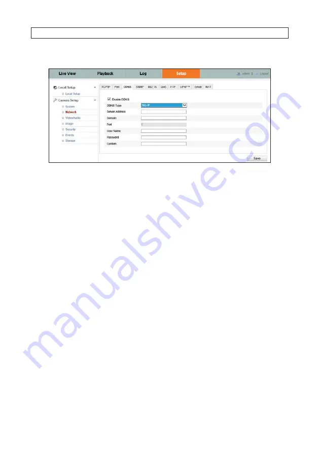
For NO-IP: 

i. 

Enter Server Address field with the Server Address.

ii. 

In the Domain text field, enter the domain name obtained from the NO-IP website.

iii. 

Enter the 

User Name

 and 

Password

 registered on the NO-IP website.

iv. 

Click 

Save

4.2.4  SNMP

You can set the SNMP function to acquire camera status, parameters and alarm information and manage the camera remotely when 
it is connected to the network. 

Before setting the SNMP, please download the SNMP software and manage to receive the camera information via SNMP port. By 
setting the Trap Address, the camera can send the alarm event and exception messages to the surveillance center.

Note: The SNMP version you select should be the same as that of the SNMP software. And you also need to use the different version 
according to the security level you required. SNMP v1 provides no security and SNMP v2 requires password for access. SNMP v3 
provides encryption. When using SNMP v3, HTTPS protocol must be enabled.

SECTION 4: CAMERA SETUP MENUS

Summary of Contents for ALI-IPU Series

Page 1: ...ies and ALI IPV Series cameras ALI IPU3013 Series Camera ALI IPV3013 Series Camera PLEASE READ THIS MANUAL BEFORE USING YOUR CAMERAS and always follow the instructions for safety and proper use Save t...

Page 2: ...representations concerning the legality of certain product applications such as the making transmission or recording of video and or audio signals of others without their knowledge and or consent We...

Page 3: ...se be advised of the following Ensure environmental conditions meet factory specifications Major shocks or jolts to the unit as a result of dropping it may cause damage to the sensitive electronics wi...

Page 4: ...iv...

Page 5: ...over 4 2 1 1 Restore Default Password 6 SECTION 3 Remote Access 7 3 1 Remote login 7 3 2 Remote LiveView screen 11 3 3 Playback screen 12 3 4 Remote Log screen 16 3 5 Remote Configuration screen 16 3...

Page 6: ...erlay 39 4 4 4 Privacy Mask 40 4 5 Security menus 41 4 5 1 User 41 4 5 2 RTSP Authentication 43 4 5 3 AnonymousVisit 43 4 5 4 IP Address Filter 44 4 6 Events menus 45 4 6 1 Motion Detection 45 4 6 2 V...

Page 7: ...on an IP network and connected directly by a PC with a Video Management System VMS Since the Alibi camera is an IP based device several other application configurations are also possible Important co...

Page 8: ...a network based storage device such as a Network Attached Storage NAS device or a device using Server Message Block SMB or Common Internet File System CIFS protocol With this configuration the camera...

Page 9: ...er should meet the following requirements Operating System Microsoft Windows XP SP1 and above Windows Vista 7 Server 2003 Server 2008 32 bit CPU Intel Pentium IV 3 0 GHz or faster RAM 1GB or more Disp...

Page 10: ...d change their network settings The tool is provided on the software CD with your camera To use the tool 1 Insert the software CD provided with your camera into an optical drive on the Microsoft Windo...

Page 11: ...ETWORK CONNECTION 5 To change the network settings of the camera to be compatible with the subnet where it is installed do the following a Click the device to highlight it Notice that the network para...

Page 12: ...1 Restore Default Password The Alibi Discover Tool includes a feature in the lower right corner of the screen labeled Restore Default Password This feature is a Support only tool that allows them to...

Page 13: ...e that some user permissions disallow features remote access to the camera When logging into the camera from a remote computer for the first time you must install a plug in program named WebComponents...

Page 14: ...era at this IP address AND you are using Internet Explorer 10 or newer you must configure it for Compatibility mode a In Internet Explorer click the Tools icon located to the right of the tabs then se...

Page 15: ...is the first login to an Alibi camera from your computer and browser continue with the following sub steps to install WebComponents a After a successful login to the NVR a message will appear in the m...

Page 16: ...me thenclickRunAnyway b In the Setup WebComponents window opens click Next to continue Installing the WebComponents plugin may require that you close the browser Follow the on screen instructions then...

Page 17: ...ing options Click the appropriate button to select a 4 3 or 16 9 aspect ratio full size X1 button and Sub Stream or Main Stream Capture Record Enable e PTZ icons Screen select tabs Live View options L...

Page 18: ...resets is presented beneath the control panel on the right side of the screen Switch from window mode to full screen mode by double clicking anywhere in the Live View video window To return to window...

Page 19: ...button Recorded video is indicated by a colored band on the timeline The color legend is shown below the timeline You can expand or contract the timeline with the icons on the right At the bottom of...

Page 20: ...on page 17 for more information To download a video recording In the Playback screen Click the Download recording icon In the options on the right panel select the type of recording you want to downlo...

Page 21: ...download images In the Playback screen Click the Download images icon In the options on the right panel select the type of images you want to download the Start Time and the End Time when the recordi...

Page 22: ...rt Log reports can be saved in either text or Excel formats by clicking the Save Log icon 3 5 Remote Configuration screen Open the Configuration screen by clicking the Configuration tab The Configurat...

Page 23: ...audio and video streams HTTP Allows the same quality as of TCP without setting specific ports for streaming under some network environments MULTICAST See TCP IP settings for more information Live Vie...

Page 24: ...the saving path of the manually captured pictures in Live View mode Save snapshots when playback to Set the saving path of the captured pictures in playback mode Save clips to Set the saving path of...

Page 25: ...below Camera Setup System Video Audio Network Image Security Events Maintenance Time Settings Device Information Service DST Anonymous Visit RSTP Authentication User IP Address Filter Text Overlay OSD...

Page 26: ...vice Information In the Device information screen you can change the Device Name and number by editing the fields then clicking Save 4 1 2 Time Settings Use the Time Settings screen to set the correct...

Page 27: ...ions with NTP server NOTE Ifthecameraisconnectedtoapublicnetwork useaNTPserverthathasatimesynchronizationfunction suchastheserveratthe NationalTimeCenter IPaddress 210 72 145 44 Ifthecameraissetinanis...

Page 28: ...NCLUDING the IP network settings and user information to their factory default values The network IP address is reset to 192 0 0 64 Export Click Export to save the camera configuration file for Import...

Page 29: ...elect either Firmware or Firmware Directory In the example below Firmware was selected 2 Click Browse then browse to the firmware file for Firmware or the directory where the firmware file exists for...

Page 30: ...DST box then set the Start Time and End Time using the options in the drop down lists 3 Click Save 4 1 5 Service The Service menu allows you enable or disable the IR light and Telnet Depending on the...

Page 31: ...twork TCP IP 2 Configure the basic network settings including the NIC Type IPv4 or IPv6 Address IPv4 or IPv6 Subnet Mask IPv4 or IPv6 Default Gateway MTU settings and Multicast Address Notes The valid...

Page 32: ...can be changed to any port range 1024 to 65535 RTSP Port The default port number is 554 HTTPS Port The default port number is 443 and can be changed to any port range 1024 to 65535 Server Port The de...

Page 33: ...preferred DNS These values can be obtained from your Internet Service Provider ISP i In the Server Address field enter static IP address of the computer that runs the IP Server software ii Click Save...

Page 34: ...network Before setting the SNMP please download the SNMP software and manage to receive the camera information via SNMP port By setting the Trap Address the camera can send the alarm event and excepti...

Page 35: ...quires an authenticator authentication device and typically an authentication server The authenticator is a network device such as an Ethernet switch or wireless access point and the authentication se...

Page 36: ...o be in effect 4 2 6 QoS QoS Quality of Service can help solve network delay and network congestion problems by configuring the priority of sent data To open the QoS screen go to Setup tab Network QoS...

Page 37: ...ent directory or child directory When the parent directory is selected you have the option to use the Device Name Device Number or Device IP for the name of the directory and when the Child Directory...

Page 38: ...edit the Friendly Name field if necessary then click Save to retain your settings You can verify UPnP functionality by opening a file browser then looking at the items listed in the Network directory...

Page 39: ...y the SMTP server Attached Image Check this box if you want to send email with an image Interval The interval is the time between two emails sent wiht attached pictures Authentication optional If your...

Page 40: ...ity concerns 4 3 Video Audio menus 4 3 1 Video The Video menu is used to setup the Main Stream video transmission settings and Sub Stream settings for dual stream cameras In this example the camera ha...

Page 41: ...G Profile The profile for this camera is Main Profile No other profiles are selectable I Frame Interval Set the I Frame interval to 1 400 The I frame interval represents the rate at which the entire v...

Page 42: ...the Fixed Region box for Fixed Region encoding Clear the box for Dynamic Tracking If you enabled Fixed Region you can also select the Region number 1 3 the ROI Level Image Quality Enhancing level and...

Page 43: ...Display Settings menu go to Setup tab Image Display Settings Configurable parameters include Switch Day and Night Select either Auto Switch or Scheduled Switch If using Auto Switch open the Day Night...

Page 44: ...filtering time and Smart IR Schedule Use Schedule to set that Start Time and End Time for the switch Smart IR is also selectable Backlight Settings Backlight settings include BLC Area Off Up Down Lef...

Page 45: ...o to Setup tab Image OSD Settings 1 Check the corresponding box to select the display of camera name date or week if needed 2 Edit the Camera Name if needed 3 From the drop down lists select the prefe...

Page 46: ...xt box to the location on the image where you want it displayed 3 Click Save 4 Repeat the steps above for the text labels as needed You can add up to four labels to one image 4 4 4 Privacy Mask The Pr...

Page 47: ...nts and change passwords To use this menu you must log into the camera with the admin user credentials In the User menu you can create either of two levels of users Operator and User Each level has a...

Page 48: ...user 1 In the User menu click Add 2 In the User Name field enter a unique user name You can enter most keyboard characters to compose the name 3 In the Level drop down list select either Operator or U...

Page 49: ...using RTSP protocol with the IP address of the camera The default setting is Basic authentication requires credentials To open the RTSP Authentication menu go to Setup tab Security RTSP Authenticatio...

Page 50: ...Enable IP Address Filter box 2 In the IP Address Filter Type field open the drop down list and select either Allowed To enable clients at only specific at IP address to access the camera Forbidden To...

Page 51: ...n Normally motion detection recording is performed by an NVR or VMS device that monitors the video stream from the camera and is configured to record when motion is sensed However for configurations w...

Page 52: ...ar All to reset the motion detection area b Click Draw Area c Using the mouse drag a rectangle across the area of the image where you want to sense for motion You can select multiple areas d Click Sto...

Page 53: ...ap In the example above one period was setup for Monday then copied to every other day of the week 5 When finished setting up the schedule click OK The Arming schedule configured above is shown in the...

Page 54: ...vered To configure video tampering you must designate an area that is sensed for video tampering then setup a schedule when the camera senses for that condition To open the Video Tampering menu go to...

Page 55: ...ap In the example above one period was setup for Monday then copied to every other day of the week 7 When finished setting up the schedule click OK The Arming schedule configured above is shown in the...

Page 56: ...larm when a state change is detected on the camera alarm input terminals The alarm input terminals can be configured for Normally Open NO or Normally Closed NC The alarm is armed only when enabled in...

Page 57: ...configuration you setup for this alarm input to other alarm inputs by checking the appropriate boxes in the Copy to Alarm section 6 In the Arming Schedule section of the window click the Edit button 7...

Page 58: ...or upload a screen capture to an FTP server check the appropriate box Note that the Email configuration see 4 2 9 Email on page 32 and FTP server configuration see 4 2 7 FTP on page 31 must also be s...

Page 59: ...eld open the drop down list and select duration of the alarm output is active You can select either 5 10 or 30 seconds 1 2 5 or 10 minutes or Manual 4 For cameras with multiple alarm outputs you can c...

Page 60: ...ay and period then edit the field for then time Note that periods cannot overlap In the example above one period was setup for Monday then copied to every other day of the week 7 When finished setting...

Page 61: ...tain your settings 4 6 5 Exception Exception types are certain abnormal events that are sensed by the camera When these events occur the camera can send an Email alert signaling that some maintenance...

Page 62: ...recording before the scheduled time or the event For example if an alarm triggers recording at 10 00 and the pre record time is set as 5 seconds the camera starts to record at 9 59 55 b Open the Post...

Page 63: ...list and select the kind of recording you want to perform ii If you selected Customize click the Start Time field for Period 1 then enter the start time hours and minutes Repeat for the End Time field...

Page 64: ...rage Management menu you can prepare external storage for use Format and set the percentages of Pictures Captures and Video recordings across the storage device This menu is only useful after the you...

Page 65: ...format of the HDD erases all data from the disk b Wait until Format completes before continuing When Format completes the HDD status will change to Normal 3 Edit the percentages of the HDD allocated f...

Page 66: ...of the server the File Path in the entry fields c In the Mounting Type drop down list select either NFS or SMB CIFS for the device type you want to add d If you select SMB CIFS in the type field enter...

Page 67: ...ic and event triggered screen captures of video from the camera Screen captures are save to the NAS storage device you configured to an FTP server with the Upload Picture option is selected see 4 2 7...

Page 68: ...shots are when an event such as Motion Detection occurs a Check the Enable Event Triggered Snapshot box b Open the Quality drop down list and select either Low Medium or High c Select the Interval tim...

Reviews: