background image

10 


Figure 7a  


Figure 7b 

-


It is preferable to install an R1" multistage pump with a flow rate capacity that always meets current system needs. 
Install  block  valves  immediately  downstream  and  upstream  of  the  pump  to  enable  removal  of  pump  for  repairs, 
replacement etc. without discharging the water from the system. 

-


Install the spigot used for filling and discharging the system on the return pump at the lowest point of the system. 

-


Prior to startup, fill the system with water as follows: 

a)


for open circuits, fill the system using the spigot for filling and discharge, until the water starts to leak from the expansion 
vessel’s overflow pipe, 

b)


for closed circuits, system pressure (operating pressure) should be 0.1 

 0.15 mPa (1 

 1.5 bar). 

 
In  both  cases,  slowly  fill  the  system  so  that  air  can  escape  through  air  release  valves.  If  the  valves  are  not  opened 

automatically, open them manually until water starts to leak, and then close them. 

-


Do not discharge water from the heating system even during summer, because it protects the inside of the system 
from oxidation (corrosion). 

-


If you will not use the boiler for a longer period during winter and no antifreeze mixture is pored into the system, it is 
best  if  you  discharge  water  from  the  system.  While  discharging  the  system,  open  the  radiator  valves,  air  release 
valves and other system blocking elements. 

-


You may not light a fire if water in the boiler is frozen or if there is not enough water in the boiler. 


9.


STARTUP AND LIGHTING THE FIRE 

 
Before you light the fire for the first time, the entire local (central) heating system should be filled with water and well bled, 

and the stove should be properly connected to the chimney, as described in the foregoing items. 

NOTE: The stove may not be used without water. It must be connected to the system, which is connected to consumers 

(radiators) with the power of no less than 14 KW. 

When the system is cold, power regulator (combustion regulator, thermostat) damper located on the ash pan door (Fig. 1, 

Items 10 and 19) should be open. Pull out the damper open and close knob (Fig. 1, Item 4 and Fig. 15). This opens the damper 
and enables you to light the fire. Later, when the fire has been burning for a while, set the damper to an appropriate position, 
depending on the chimney draw and desired power, and push the knob back. This closes the damper and enables maximum 
yield of combustion and thereby better heating, cooking and  baking. During this process, fire box and ash pan door  (Fig. 1, 
Items 7 and 9) must be closed, if you need controlled burning. Fire lighting damper is opened only while the fire is being lit (10 
to 15 minutes). 

Fire is lit in the stove the same way as in other solid fuel stoves. Fire is lit with the ash pan door and grate holder open (Fig. 

9 and Fig. 10). Grate holder (Fig. 1, Item 13 and Fig. 9) is opened by lifting and pulling. When the fire starts burning, you may 
load wood, but do not fill the firebox at once and divide the fuel necessary to fill the firebox in two or three portions and load 
them  into  the  firebox  in  10 

  15  minute  intervals.  A  stove  loaded  in  such  way  can  burn  for  1  to  6  hours,  depending  on 

combustion strength in the stove or on the regulator (thermostat) setting. 


Figure 9  


Figure 10 


Figure 11 

 
The firebox can also be filled from the cooktop (Fig 12). Lift the cooktop lid using a wrench and load the fuel. 
It  is  not  recommended  to  burn  organic  or  other  waste  in  the  stove  (plastic  bags,  bones,  etc.)  because  this  causes 

formation of tar deposits on the flue duct walls, which can cause a fire. 

Summary of Contents for ALFA TERM -27

Page 1: ...ALFA TERM 27 This product meets the requirements of the Ecodesign Directive in terms of efficiency and air pollution level in order to contribute to the reduction of energy consumption and negative en...

Page 2: ...eating power is shown for stoking dry beech wood with lower heating power Hd 4255W kg DEAR BUYERS Thank You for the trust you showed us buying our stove for floor heating We assure You that You have c...

Page 3: ...2 1 THERMAL VALVE WITH BUILT IN THERMAL PROTECTION Fig 7 Item 13 and Fig 7a 7 7 2 2 SLOPE PRESSURE REGULATOR 1 2 WITH MANOMETER Fig 7 Item 19 and Fig 7b 8 7 2 3 WATER FILTER OF THE BOILER INTAKE Fig...

Page 4: ...CKAGING MAY CAUSE SUFFOCATION THESE INCLUDE PLASTIC BAGS FILMS STYROFOAM ETC 2 3 THE RESPONSIBILITY OF THE INSTALLER The responsibility of the installer is to perform all the checkups of the flue pipi...

Page 5: ...Secondary air regulator knob 19 Ash pan door 10 Thermostat combustion regulator knob 12 Ash pan ash box 13 Grate holder 14 Wood box 15 Cleaning access plate 16 Pressure gauge 17 Thermometer 18 Cooktop...

Page 6: ...inet is mounted above the stove minimum clearance between the stove s cooktop and the cabinet should be at least 40 cm Combustible materials e g wallpapers door casings doors etc require a clearance t...

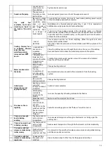
Page 7: ...box and screw it on the outlet on the cooktop or on the side outlet First remove the cover and use the same screws to fasten the collar NOTE If your chimney is of unsatisfactory or dubious quality we...

Page 8: ...is built on the outside walls it must be well insulated If the chimney connection is tightly connected to the chimney if the connection is extended If it is properly cleaned and free of birds nests di...

Page 9: ...ney pipes that have a rectangular internal cross section with a ratio that differs from the plan Modest efficiency 40 Chimney positioning and distance 7 INSTALLING THE STOVE IN THE WATER HEATING SYSTE...

Page 10: ...ssure regulator with manometer 1 2 the same or similar as shown in Fig 7b and Fig 7 Item 19 3 Filter for cold water at the input of the water supply to the thermal valve Fig 7 Item 20 4 Filter for hot...

Page 11: ...the hot boiling water from dirt and solid objects that can damage the tap seals or seals of the thermal valve This filter must be resistant to water temperatures up to 150 C NOTES After the completio...

Page 12: ...losed expansion vessel 7 Contact thermostat Note It is mandatory to install a thermal discharge valve with thermal protection the so called thermal fuse in accordance with the recommendations from the...

Page 13: ...ected to the chimney as described in the foregoing items NOTE The stove may not be used without water It must be connected to the system which is connected to consumers radiators with the power of no...

Page 14: ...d using the thermostat power regulator combustion regulator which is located in the ash pan door and which automatically sets the regulator damper depending on the regulation knob setting Fig 1 Items...

Page 15: ...odors the next time you heat the oven Clean the cooktop occasionally using fine sandpaper and in the event of longer breaks apply acid free oil on the cooktop vegetable oil Remove burnt material from...

Page 16: ...t If water is leaking from the valve replace the expansion vessel If only air comes out from the valve remove the installation vessel and pump it The pressure in the vessel must be equal to or greater...

Page 17: ...small number of radiators are switched on Transfer the grate to upper position or switch on some other radiator Keep the ashtray door closed 14 Water condensate in the boiler Damp heating material Cha...

Page 18: ...ate of undesirable objects 18 Outline dimensions of ALFA TERM 27 stove Figure 16 19 DETERMINING THE REQUIRED HEAT OUTPUT There is no absolute rule that would allow the calculation of the required heat...

Page 19: ...eating close the air inlet covers and DO NOT open the fireplace door Extinguish the fire with appropriate means home fire extinguisher NEVER USE WATER TO EXTINGUISH THE FIRE Also notify local firefigh...

Reviews: