


5 Maintenance
Take care not to damage shaft surfaces, in particular where bearings and lipseals will be located
Ensure all fastenings are tightened to the torque settings as shown in Technical Data (See chapter 6 Technical data)
S
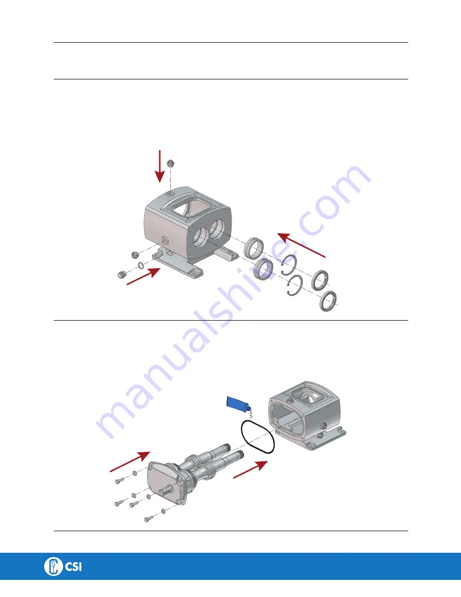
Stteepp 55
Assembling of gearbox. Ensure correct torques are used.
1. Tap the needle bearing outer races into their seat.
2. Fit needle bearing snap ring.
3. Fit lip seals.
4. Fit filler plug.
5. Fit oil sight glass.
6. Fit drain plug and washer.
3205-0033
S
Stteepp 66
Assembling of gearbox. Ensure correct torques are used.
1. Fit gearbox O-Ring use grease to keep it in place.
2. Push in the shaft assembly into the front gearbox. (take care not to damage the lip seals ). Ensure that the drive shaft is
in the correct position to realign with the motor coupling.
3. Fit the gearbox end cover bolts and washers and torque them to their recommended value.
4. Fit drive shaft key.
3205-0034
33
CONTACT CSI FOR MORE INFORMATION | CSIDESIGNS.COM | [email protected] | 417.831.1411


