background image

2600 series Hydraulic Tooling 

(HK914)

Alcoa Fastening Systems

14

Always check the simplest possible cause of a
malfunction first (example: a loose or disconnected
trigger line).  Then proceed logically and eliminate
each possible cause until the defect is found.
Where possible, substitute known good parts for
suspected defective parts.  Use the following steps
as an aid in troubleshooting.

1. 

Tool fails to operate when trigger is pressed.

a. Inoperative POWERIG® Hydraulic Unit.  See

applicable instruction manual.

b. Loose electrical connections.
c. Damaged trigger assembly.
d.  Loose or faulty hose coupling.

2. 

Tool operates in reverse.

a. Reversed hose connections between hydraulic

unit and tool.

3.

Tool leaks hydraulic fluid.

a. Defective tool O-rings or loose connections at

tool.

4. 

Hydraulic couplers leak fluid.

a. Damaged or worn O-rings in Coupler Body

Coupler 

5.

Hydraulic fluid overheats.

a. Unit not operating properly. See units manual.
b. Unit running in reverse (918; 918-5 only). See

unit’s manual.

6.

Tool operates erratically and fails to install
fastener properly.

a. Low or erratic hydraulic pressure. Air in

system.

b. Damaged or worn Piston O-ring in tool.
c. Excessive wear on sliding surfaces of tool

parts.

7.

Pull grooves on fastener pintail stripped during
PULL stroke.

a. Operator not sliding anvil completely onto

fastener pintail.

b. Incorrect fastener grip.
c. Worn or damaged jaw segments.
d. Metal particles in jaw grooves.
e. Excessive sheet gap.

8. 

Collar of fastener not completely swaged.

a. Improper tool operation. See No. 6.
b. Scored anvil.

9. 

Tool "hangs up" on swaged collar of fastener.

a. Improper tool operation. See No. 6.
b. RETURN pressure too low.
c. Not enough collar lubricant.
d. Nose assembly not installed correctly.

10. 

Pintail of fastener fails to break.

a. Improper tool operation - - see No. 6.
b. Pull grooves on fastener stripped - - see No. 7.
c. PULL pressure too low.

11. 

Nose will not release broken pintail.

a. Nose assembly not installed correctly.

Service Kit:

All Models

-  2600KIT

Assembly Tool Kit:

Assembly Tool Kit: All Models

- 123110

Includes: (Figs. 3 & 6))

Spacer   

- 123112

Piston Assembly Tool

- 123111

GLYD Ring Insertion Tool

- 121694-2600

T

T

ROUBLESHOOTING

ROUBLESHOOTING

K

K

ITS

ITS

 & A

 & A

CCESSORIES

CCESSORIES

Summary of Contents for Huck 2600 Series

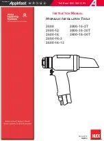
Page 1: ...MANUAL HYDRAULIC INSTALLATION TOOLS 2600 2600 2600 16 2T 2600 16 2T 2600 12 2600 12 2600 16 30T 2600 16 30T 2600 16 2600 16 2600 16 50T 2600 16 50T 2600 16 3 2600 16 3 2600 16 12 2600 16 12 Toll Free...

Page 2: ...2600 series Hydraulic Tooling HK914 Alcoa Fastening Systems 2...

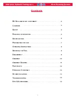
Page 3: ...CONTENTS 3 SAFETY 4 PRINCIPLE OF OPERATION 5 SPECIFICATIONS 6 PREPARATION FOR USE 7 OPERATING INSTRUCTIONS 8 SERVICING THE TOOL 8 DISASSEMBLY 9 ASSEMBLY 10 ASSEMBLY DRAWING 11 PARTS LISTS 12 HYDRAULIC...

Page 4: ...fastener ejecting may occur 17 Where applicable always clear spent pintail out of nose assembly before installing the next fastener 18 There is possibility of forcible ejection of pintails or spent ma...

Page 5: ...stalling the fastener When the Piston reaches the end of the PULL stroke it uncovers flats on the back of the Dump Valve These flats are designed to provide a passage for hydraulic fluid from the PULL...

Page 6: ...ison C 4 or equivalent specifications Fire resistant hydraulic fluid may also be used and is required to comply with OSHA regulation 1926 302 paragraph d the fluid used in hydraulic power tools shall...

Page 7: ...E SE WARNING Correct PULL and RETURN pressures are required for operator s safety and for Installation TooI s function Pressure Gauge T 124883CE is available for checking pressures See Tool SPECIFICAT...

Page 8: ...res in this manual SYSTEM INSPECTION Operating efficiency of the installation tool is directly related to performance of the complete system including the tool with nose assembly hydraulic hoses trigg...

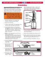
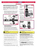
Page 9: ...eflector Assembly 14 by twisting and pulling in the same motion 7 Remove Socket Head Screw 12 and Barbed Retainer 13 from Rear Gland 11 8 Insert two 5 16 pins in opposite holes in rear of Barbed Retai...

Page 10: ...18 and Retaining Ring 19 in Rear Gland 11 Fig 5 11 Lubricate inside of assembled Rear Gland Assy and press into Cylinder 12 Press Wiper 15 into groove in Rear Gland 13 Align recess in Rear Gland with...

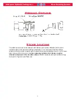
Page 11: ...0 12 only 22 2 24 23 2 32 33 Sticker Locations NOTE REVERSAL OF HOSE FITTING LOCATION OF 2600 16 2T 2600 16 30T 2600 16 50T 2600 2600 12 2600 16 2600 16 3 2600 16 12 2600 16 2T 2600 16 30T 2600 16 50T...

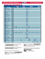
Page 12: ...600 12 2600 16 2600 16 3 2600 16 12 2600 16 2T 2600 16 30T 2600 16 50T 1 Piston 1 122759 1 125467 2 2 Retaining Nut 1 122756 3 Front Wiper Seal 1 505064 4 Front Wiper Housing 1 122758 5 Back up Ring 2...

Page 13: ...part number 590424 7400 which contains safety and pressure settings information It is necessary that this sticker remain on the tool and is easily read If sticker becomes damaged or worn or if it have...

Page 14: ...l operates erratically and fails to install fastener properly a Low or erratic hydraulic pressure Air in system b Damaged or worn Piston O ring in tool c Excessive wear on sliding surfaces of tool par...

Page 15: ...y 90 day warranty period for tooling other items nonstandard or custom products described above and Huck shall inspect products for which such claim is made TOOLING PART S AND OTHER ITEMS NOT MANUFACT...

Page 16: ...applifast com 251 Cree Crescent Winnipeg MB Canada R3J 3X4 Tel 204 837 8361 1 800 563 1293 Fax 204 837 3520 1 800 974 1494...

Reviews: