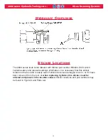
POWER SOURCE CONNECTIONS
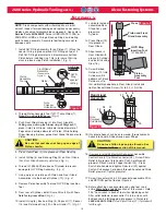
Coat hose fitting threads with a non-hardening
Teflon
TM
thread compound such as Slic-tite.
TM
1. Use Huck POWERIG
®
Hydraulic Unit, or
equivalent, that has been prepared for operation
per applicable instruction manual. Check both
PULL and RETURN pressures, and if required,
adjust to pressures given in
S
S
PECIFICATIONS
PECIFICATIONS
.
2. First, turn hydraulic unit to OFF, and then,
disconnect power supply from unit. Connect
tool's hoses to Powerig unit.
3. Connect tool's control switch electrical cord to
hydraulic unit.
4. Connect hydraulic unit to power supply. Turn
unit to ON. Hold tool trigger depressed for 30
seconds; depress trigger a few times to cycle
tool and to circulate hydraulic fluid. Observe
action of tool and check for leaks. Turn unit to
OFF.
5. Select nose assembly for fastener to be
installed. Disconnect tool's control switch
electrical cord from hydraulic unit; disconnect
unit from power supply. Attach nose assembly
to tool.
6. Reconnect hydraulic unit to power supply.
Reconnect tool's switch control cord to unit.
Check operation of nose assembly; install
fasteners in test plate of correct thickness with
proper size holes. Inspect installed fasteners. If
fasteners do not pass inspection, see
T
ROUBLESHOOTING
to locate and correct tool
malfunction.
WARNING: Be sure to connect Tool’s
hydraulic hoses to POWERIG Hydraulic
Unit before connecting Tool’s switch
control cord to unit. If not connected in
this orderand disconnected in the
reverse order, severe personal Injury
may occur.
2600 series Hydraulic Tooling
(HK914)
Alcoa Fastening Systems
7
P
P
REPARATION
REPARATION
FOR
FOR
U
U
SE
SE
WARNING: Correct PULL and
RETURN pressures are required for
operator’s safety and for Installation
TooI’s function. Pressure Gauge T-
124883CE is available for checking
pressures. See Tool S
PECIFICATIONS
and Gauge Instruction Manual.
Failure to verify pressures may result
in severe personal injury.
WARNINGS:
Read full manual before using tool.
A half-hour training session with qualified
personnel is recommended before using
Huck equipment.
When operating Huck installation equipment,
always wear approved eye and ear protection.
Be sure there is adequate clearance for the
operator’s hands before proceeding.
*
Slic-Tite is a registered trademark of LA-CO Industries, Inc.
*
TEFLON is a registered trademark of DuPont Corp.
*
LUBRIPLATE is a registered trademark of LUBRIPLATE Lubricants Co.
GOOD SERVICE PRACTICES
Sealants, Lubricants, Hydraulic Fluid &
Service Kits
•
Rub Slic-Tite TEFLON thread compound, or
equivalent, on pipe threads to prevent leaks
and for ease of assembly.
•
Smear LUBRIPLATE
®
*
No. 130-AA, or
equivalent, on O-rings and mating surfaces to
prevent damaging O-rings on rough or sharp
surfaces. Also, increases ease of assembly.
(LUBRIPLATE in a tube, 502723).
CAUTION: Do not let disconnected hoses and
couplers contact a dirty floor. Keep harmful
material out of hydraulic fluid. Dirt in
hydraulic fluid causes valve failure In Tool
and In POWERIG Hydraulic Unit.
CAUTION: Do not use TEFLON
®
* tape on pipe
threads. Pipe threads may cause tape to shred
resulting in tool malfunction. (Slic-Tite is
available in stick form as Huck P/N 503237.)
Huck recommends that only Huck Powerig
Hydraulic Units be used as a power source
for Huck installation equipment. Hydraulic
power units that deliver high pressure for
both PULL and RETURN, AND ARE NOT
EQUIPPED WITH RELIEF VALVES ARE
SPECIFICALLY NOT RECOMMENDED AND
MAY BE DANGEROUS.

