background image

Subject to changes in line with technical progress.

49

3059570

Integrated control

7.1 

HMI Basic quick start guide

ART Tech Level II 

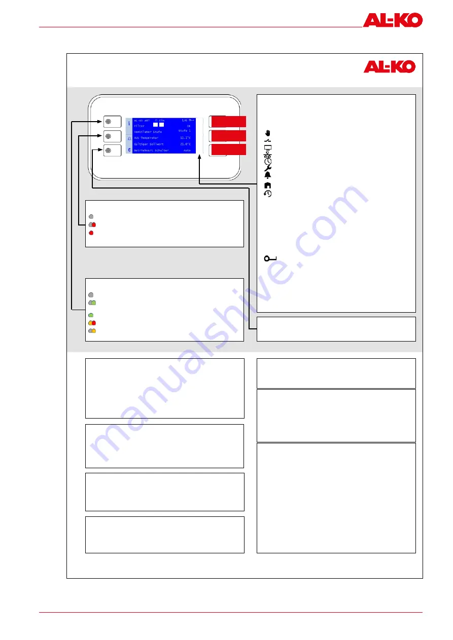
Quick Guide HMI Basic (Room Control Panel)

UP arrow key

DOWN arrow key

ENTER button

Switch on the plant using the control panel (user password required)

1.  Use 

INFO

 to access the 

start page

. Select 

Operating mode

 with the 

arrow 

keys

 and press 

ENTER

.

2.  Use the 

arrow keys

 to mark the required 

operating mode

 and press 

ENTER

.

Plant information

Use 

INFO

 to access the 

main menu

. Select 

Information

 with the 

arrow keys

 and 

press 

ENTER

.

See the operating manual for a description of the individual items.

Setting the temperature setpoint (user password required)

1.  Use 

INFO

 to access the 

main menu

. Select 

Setpoints

 with the arrow keys and 

press 

ENTER

.

2.  Go to 

Temp control

 with the 

arrow keys

 and press 

ENTER

.

3.  Select 

Comfort setpoint

 or 

Economy setpoint

 with the 

arrow keys

 and press 

ENTER

. Now change the value with the 

arrow keys

 and confirm again with 

ENTER

.

Setting the timer program (user password required)

1.  Use 

INFO

 to access the 

main menu

. Select 

Time program

 with the arrow keys 

and press 

ENTER

.

2.  Recommendation: Set the switching times for 

Monday

 and copy it to the other 

days. To do this, select 

Monday

 with the 

arrow keys

 and press 

ENTER

.

3. 

 Time 1

 is fixed to 

00:00 

and cannot be changed. For 

Value 1

off

 is recom-

mended as otherwise the plant starts at 00:00. 

Use the 

arrow keys

 to go to 

Time 2

 or 

Value 2

 and press 

ENTER

. Use the 

arrow keys to send the morning compensation time (e.g. 

07:00

) and the oper-

ating mode (e.g. 

Stage 1

).

4.  Set the other value/time pairs in the same way. Leave unused switching times 

at 

*:*

Set a corresponding 

value … 

to 

off

 as the shut-down time.

5.  If necessary, copy the time switching catalogue from 

Monday

 to other days. 

To do this, use the 

arrow keys

 to go to “Copy schedule” and press 

ENTER

. Use 

the 

arrow keys

 to select the destination (e.g. 

Tues-Fri

 for Tuesday to Friday) 

and confirm with 

ENTER

. The time switching catalogue is copied.

Important information!

1.  The number of plant steps and the availability of the economy mode depend on 

the configuration of the plant (see operating instructions).

2.  In economy mode, the plant is operated at a reduced temperature setpoint. See 

the operating manual for further information.

Password entry

1.  Press 

INFO

 to access the 

main menu

. The topmost entry is the 

password 

enter

. Press 

ENTER

.

2.  A password consists of four numbers. Each number is set separately with the 

arrow keys

 and confirmed with 

ENTER

Enter the user password 

1 0 0 0 

After entering the password correctly, a key symbol appears at top right of the 

display. 

3.  Other passwords levels are described in the operating manual.

Acknowledging alarms (only when alarms are pending)

1.  Press 

ALARM

; the 

alarm list detail

 appears.

2.  Then press 

ALARM

 again; the 

alarm list

 appears. The topmost entry is 

Ac-

knowledge

. Press 

ENTER

.

3.  Select 

Execute

 with the 

arrow keys

 and press 

ENTER

 again. The acknowledge-

ment attempt is started.

2

1

3
4
5
6
7
8

Display on the start page

If no button is pressed for a few minutes, the display jumps to the main menu. 

Press 

INFO

 to go to the start page with the most important plant information.

1. State

Plant switched on control panel (HMI Basic, Facility, Web)

Plant switched via external enable (e.g. presence sensor)

Plant switched on the room control panel (HMI Room)
Plant switched via the building management system
Plant switched via the time program

Plant OFF: Configuration is not complete

Plant OFF: switched off alarm or emergency stop
Plant ON: Free cooling, cool-down or overheating protection

Plant ON: early start before time program (boost)

2. Operating mode

Off

Plant OFF

Start

Plant is starting up (dampers open, pre heating)

On

Plant ON

Comfort

Plant ON in comfort mode

Economy

Plant ON in economy mode

Run-on

Plant follow-up (humidifier/electrical heating coil)

3. 


Display of the logged-in password level

4. Filter alarm 

Display of the filter state (depending on the equipment 

of the plant, the degree of soiling in percent is also 

displayed).

5. Fan steps 

Display of the current fan steps

6. Outside air temp 

Display of the current outdoor temperature

7. Valid setpoint 

Display of the current valid temperature setpoint

8. Operating mode switch  Switching of the operating mode on the control panel

ESCAPE button

Press this button to return to the previous menu item.

INFO button with integrated INFO-LED

Off:

 Plant off

Green flashing: 

Plant starts (dampers open, preheating) or running 

on (humidifier drying, electric heating cooling)

Green:

 Plant on

Orange/red flashing:

 Manual mode active

Orange flashing: 

Plant not functional as not fully configured

ALARM button with integrated ALARM LED

Off: 

No alarm; press to go directly to the 

alarm history

.

Red flashing:

 Alarm

Red: 

Alarm is still active; an attempt has been made to ac-

knowledge it

3421375

Summary of Contents for EASYAIR flat EF-01

Page 1: ...EN OPERATING AND ASSEMBLY INSTRUCTIONS AL KO EASYAIR flat FLAT AIR HANDLING UNIT...

Page 2: ...bH Hauptstra e 248 250 D 89343 Jettingen Scheppach Germany Telephone 49 8225 39 0 Fax 49 8225 39 2113 E mail klima technik al ko com Revision history Version Description Date 1 0 Initial release 01 12...

Page 3: ...orage prior to assembly 17 4 3 Transport 17 4 4 Transport under difficult conditions 18 4 5 Disposal of packaging 19 5 Assembly 20 5 1 General information 20 5 2 Preparations 21 5 3 Ceiling constructi...

Page 4: ...control 48 7 1 HMI Basic quick start guide 49 7 2 HMI Room quick start guide 50 8 Servicing and maintenance 51 8 1 Safety instructions for servicing and maintenance 51 8 2 Fuses and terminal assignmen...

Page 5: ...d assembly instructions are a permanent part of the described product and must be handed over to the buyer if the product is sold 1 1 Explanation of symbols 1 1 1 Safety instructions DANGER This signa...

Page 6: ...pping If the required safety instructions are not observed this can lead to death or severe injuries due to slipping Warning of electrical voltage If the required safety instructions are not observed...

Page 7: ...e is a risk of foot injuries Wear hand protection If you do not wear hand protection there is a risk of hand injuries Wear head protection If you do not wear head protection there is a risk of head in...

Page 8: ...ting breathable air Only operate the EASYAIR flat unit fully assembled Protect the unit from moisture Only use original spare parts from AL KO THERM Children and people who are not familiar with the u...

Page 9: ...ons in these operating and assembly instructions Use only tested ladders scaffolding or suitable platforms Only use suitable lifting equipment Only use approved fasteners when installing the EASYAIR f...

Page 10: ...d expressly authorised to use it Personal protective equipment is required for work on the EASYAIR flat unit To avoid hazards during operation all of the owner operator s plant operating and working i...

Page 11: ...at unit must regularly train their personnel in the following subjects Observance of the operating and assembly instructions as well as the legal regulations Intended operation of the EASYAIR flat uni...

Page 12: ...brackets are factory fitted onto the unit The units with heat recovery achieve a heat recovery rate of up to 90 according to DIN EN 308 The units therefore make a significant contribution to saving en...

Page 13: ...4 3 1 5 6 4 9 7 Width Height 11 Fig 1 EASYAIR flat EF unit Components and dimensions ODA Outdoor air SUP Supply air 1 Supply air fan module 7 Connection fitting 3 Filter module 8 Multi leaf dampers 4...

Page 14: ...ulti leaf dampers 3 Filter module 9 Installation brackets 4 Sound absorber module 10 Countercurrent plate heat exchanger module 5 Heater module hot water or electric heater 11 Pan drain 6 Cooler modul...

Page 15: ...EF 02 20 5 26 8 9 34 5 14 6 21 1 35 5 55 EF 03 30 8 34 13 8 45 5 21 9 31 6 44 5 74 3 2 2 GF supply and exhaust unit with countercurrent plate heat exchanger Type Air volume 1 m h efficiency WRG 2 soun...

Page 16: ...ing by 10 K medium 6 12 C 9 Heating power for heating by 34 K medium 50 35 C 10 Heating output for heating by 14 K 400 V 50 Hz 11 Heating output for heating by 22 K 400 V 50 Hz Value requirements at n...

Page 17: ...n one year check the ease of movement of the fans bearings by turning by hand before assembly Avoid distorting the housing or other damage during storage Damage resulting from improper packaging and s...

Page 18: ...roved lifting equipment with a sufficient load capacity may be used The lifting equipment must be in perfect condition The lifting gear must be inspected for load bearing capacity and damage before us...

Page 19: ...al vibrational stresses transport by sea or in tropical subtropical countries additional packaging must be used that will protect against these par ticular influences 4 5 Disposal of packaging When di...

Page 20: ...out only by qualified staff Observe the working instructions and these operating and assembly instructions Work with care Wear personal protective equipment CAUTION Risk of crushing the limbs and cut...

Page 21: ...or exhaust openings kitchen laundry etc If possible the exhaust air must be discharged via a roof hood away from fresh air inlets windows balconies etc ATTENTION Components that come loose during tran...

Page 22: ...uirements for the acoustics struc ture borne sound insulation and correct water drainage of the condensate The ceiling construction must be able to bear the static load of the units Example of ceiling...

Page 23: ...m below 90 1 Fig 6 Clamp closure on the maintenance panels 1 Screw Step Action 1 To open remove the maintenance panels loosen the screws of all clamp closures using the supplied hexagon socket wrench...

Page 24: ...Correctly re suspend the safety ropes including the carabiners after closing the hous ings with the maintenance panels to avoid the maintenance panels falling down when re moving them again 5 4 2 Disa...

Page 25: ...the maintenance panel 1 on the opposite side so that it can be moved below the removal rail 2 and take out the maintenance panel 1 5 4 3 Assembly of the maintenance panel for the countercurrent excha...

Page 26: ...inal operating instructions 26 AL KO EASYAIR flat 2 2 1 Fig 11 Fit the maintenance panel 1 Maintenance panel 2 Removal rail Step Action 1 Fit the maintenance panel 1 into the sealing position 2 Close...

Page 27: ...pack modules 2 Fit the provided click connectors 2 into the intended opening on the front of the module 3 Always affix the enclosed sealing tape 1 flush to the unit inside edge past the click connecto...

Page 28: ...s Step Action 5 Hang the installation brackets 1 on the upper side of the housing and screw them together with the supplied fastening screws 2 and the housing 3 All installation brackets are to be use...

Page 29: ...ules into the click connectors by pressing them together It is important to ensure that the duo taptite screw 3 is threaded into the slot of the right housing bracket c NOTE To reduce the weight of th...

Page 30: ...nts from falling using opposite force Wear personal protective equipment Removing the component lock 2 1 Fig 17 Remove component lock 1 Component lock 2 Component 2 1 Fig 18 Component lock detail 1 Co...

Page 31: ...to slipping parts The blocks on the door ribs are secured against falling By moving the door ribs horizontally prevent the blocks lying on them from slipping off Wear personal protective equipment Op...

Page 32: ...handling unit and as supply air into the building The extract air is passed through the unit and to the outside as exhaust air for heat recovery With EF units the duct system directs the outdoor or ro...

Page 33: ...ipotential bonding to the unit 1 Drilling screw 4 8 x 38 6 Hexagon head bolt M6 x 30 2 Vibration absorber 7 Drilling screw 4 8 x 19 3 Washer 6 4 8 Equipotential bonding 4 Sealing washer 6 4 9 Rubber f...

Page 34: ...mm 105 mm H2 120 mm 65 mm H3 H1 H2 NOTE The installation height of the siphon must be taken into account when setting up the unit 5 6 Electrical connection Delivery options for EASYAIR flat units With...

Page 35: ...cluded with the unit documentation option with control 5 6 1 Cable lists NOTE The cable cross sections are provided with no liability The installation type installation length and any accumulations ha...

Page 36: ...mation on connecting the field devices to the EASYAIR flat unit control can be found in the circuit diagram supplied 5 6 5 Assembly connection of supply air outdoor air extract air temperature sensor...

Page 37: ...incorrect or faulty connection Only have the electrical connection carried out by an approved electrician Only have assembly servicing and maintenance carried out by qualified staff Wear personal pro...

Page 38: ...changer has an air side frost protection thermostat The additional unit must be flanged to the main device see chapter 5 5 Assembly of the modules on page 27 The feed and return lines are to be profes...

Page 39: ...ions 3 way valve 2 way valve 1 3 2 5 4 5 1 2 5 3 4 5 Fig 26 2 way valve and 3 way valve connection versions 1 PWW heater 4 Valve 2 Frost monitor 5 Recirculation pump on site 3 Valve actuator Counterfl...

Page 40: ...ve due to the risk of freezing and corrosion 5 6 8 Connection of heater cooler module option A pump hot water heater PWW and pump cold water air cooler PCW can be provided for the additional heating a...

Page 41: ...y valves 5 6 1 2 6 3 6 4 5 4 2 way 3 way valves 5 6 1 2 6 3 6 4 5 4 Fig 28 2 way valve and 3 way valve connection versions 1 PWW heater 4 Valve actuator 2 PCW cooler 5 Valve 3 Frost monitor 6 Recircul...

Page 42: ...cleaning Function Heater and cooler are integrated into the temperature control The temperature is set by controlling the cold water and hot water actuating valves ATTENTION At temperatures below free...

Page 43: ...s and actuators must be installed professionally Please note here whether a version with a 2 way or 3 way valve is to be implemented For the electrical connection of the actuator see the circuit diagr...

Page 44: ...ied out at the discretion of the heating specialist If the cooler module is the last component before the on site duct a duct side inspection opening must be provided directly on the register droplet...

Page 45: ...ct the frost protection thermostat to the switch cabinet With filter units connect the load cells to the filter monitoring on the switch cabinet Connect the corresponding valves and pumps to the switc...

Page 46: ...ceeded no commissioning may take place Observe the table with the respective vibration values see chapter 3 2 3 Vibration values of the fan impeller on page 16 Contact our customer service if necessa...

Page 47: ...he stepper motors must be addressed on the control during commissioning 4 5 3 2 1 Fig 32 Addressing flap stepper motors valve actuators 1 Direction of rotation selector Changeover Change direction of...

Page 48: ...ructions 48 AL KO EASYAIR flat 7 Integrated control NOTE Further information on the control of the EASYAIR flat unit can be found in the AL KO THERM operating and assembly instructions functional desc...

Page 49: ...access the main menu The topmost entry is the password enter Press ENTER 2 A password consists of four numbers Each number is set separately with the arrow keys and confirmed with ENTER Enter the user...

Page 50: ...ime by 1 hour Press MINUS to decrease the remaining run time by 1 hour 3 Press FAN to switch in a cycle between Stage 1 Stage 2 Stage 3 and Automatic Setting the temperature setpoint not possible in p...

Page 51: ...utes until the fan im pellers are stationary before opening the inspection doors Never brake the impellers of the fans by hand or using an object NOTE The owner operator of an air conditioning system...

Page 52: ...ge If the maximum differential pressure is exceeded replace the filter stage X 3 3 Latest filter change X 3 4 Check the hygiene condition X 4 Heat exchanger general optional 1 3 6 12 24 4 1 If cleanin...

Page 53: ...supply Repair X 5 4 Check condensate tray for soiling corro sion and function Repair X 5 5 Check function of siphon Repair X 5 6 Check the hygiene condition X 5 7 Plate heat exchanger 5 7 1 Inspect o...

Page 54: ...calcium deposits and damage If soiled components are detected during the hygiene checks these must be cleaned immediately 8 4 1 WWE KWK ATTENTION The use of high pressure water cleaners with conventio...

Page 55: ...d using a hot water high pressure cleaner The following parameters are to be observed Nozzle Flat jet nozzle Pressure max 20 bar Water volume max 450 l h Water temperature max 70 C Distance to heat ex...

Page 56: ...and maintenance of the droplet eliminator Wear personal protective equipment cut proof gloves 8 4 4 1 Maintenance The droplet eliminator can be pulled out of the housing to the side for maintenance p...

Page 57: ...s reached NOTE Do not wash and reuse used air filters always replace them Otherwise the hygienic requirements will not be met Open or fit the maintenance panel see 5 4 Opening removing the maintenance...

Page 58: ...be carried out by author ised persons Wear personal protective equipment 9 1 Contacts For all questions that you have in connection with our products please contact the manufacturer of your ventilati...

Page 59: ...mponents must be observed The information from the component manufacturers must also be followed request this information if necessary 10 2 Dismantling Dismantling must be carried out according to the...

Page 60: ...media The unit may contain media that are hazardous to health such as coolants Work with care Avoid skin and eye contact with the media do not swallow media and observe the safety data sheets Wear pe...

Page 61: ...6 1 St rfestigkeit f r Wohnbereich Gesch fts und Gewerbebereiche sowie Kleinbetriebe Immunity standard for residential commercial and light industrial environments R sistance au brouillage pour le dom...

Page 62: ...Translation of original operating instructions 62 AL KO EASYAIR flat Notes...

Page 63: ......

Page 64: ...KO THERM GMBH l Jettingen Scheppach l Germany All rights reserved for AL KO THERM GMBH as well as in the event of applications for industrial property rights This documentation or excerpts thereof may...

Reviews: