AkitikA PR-101NR Assembly Manual Download Page 22

Page 22 of 68 


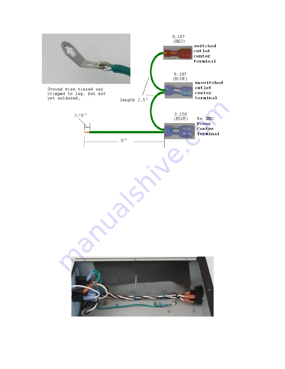
Figure 15-Adding Lug to Ground Harness 

Connecting the Chassis Ground 

Locate the #6 toothed lug. It’s packed in the “Screw Nut Lug” envelope. Locate the green 
ground harness. It has green wire with 3 FASTONs. 

1.


Cut the long green wire to 8” length as shown in Figure 15. 

2.


Remove 3/8” of insulation from the now 8” wire. Twist and tin the strands. Loop 
and crimp the wire on the lug as shown in Figure 15. Solder the wire to the lug. 

3.


Connect the blue 0.25” wide FASTON to the center terminal of the IEC power 
connector. 

4.


Connect the blue 0.187” wide FASTON to the center terminal of the unswitched 
outlet. 

5.


Connect the red 0.187” wide FASTON to the center terminal of the switched 
outlet. 

6.


Dress the long green wire toward the ground stud behind the switch as shown in 
Figure 16. Use two more cable ties in the tie down positions shown to secure the 
ground wire. 


Figure 16-AC Power and Ground Wiring 

7.


Use a plain 6-32 nut to hold the ground lug on the chassis stud. 

Summary of Contents for PR-101NR

Page 1: ...Page 1 of 68 PR 101NR STEREO PREAMPLIFIER NR No Remote Control ASSEMBLY MANUAL 2015 2018 AkitikA LLC All rights reserved Revision 1p03 October 27 2018...

Page 2: ...jumper 13 Install the voltage select jumpers 13 These Components Are Not Loaded 14 Power Supply Inspection 15 Section 4 Chassis Assembly and Power Wiring 15 Protect your PR 101 15 Install the feet 15...

Page 3: ...s 43 Install the Diodes 43 Install the Bypass Capacitors 44 Install the Integrated Circuit Sockets 44 Install the Control Cable Connector 45 Install the Relays 45 Install the Transistors 46 Install th...

Page 4: ...rods to retain the heat sink 13 Figure 6 Preparing power supply jumper wires 13 Figure 7 Install AGND to BGND jumper 13 Figure 8 Jumper installation for 120 Volt Operation left side and 240 Volt righ...

Page 5: ...C package matches silk screen feature 51 Figure 34 16 pin ribbon cable orientation and installation 52 Figure 35 Silkscreen side of the Tone Volume Board shows component locations 54 Figure 36 Remembe...

Page 6: ...e posted as of this version of the manual Tools you ll need You ll need the following tools 1 Phillips screwdriver 1 and 2 2 Pliers or nut drivers suitable for 4 and 6 hardware 3 needle nose pliers he...

Page 7: ...e hospital Read and understand the safety manuals of all the tools you use About Components We reserve the right to make design or component changes at any time without prior notification Recommended...

Page 8: ...your chances of first time success Finish one PCB before you build the next A soup bowl is your friend Before you build a board carefully empty the parts for only that board into a broad flat light c...

Page 9: ...ying the contents of the envelope marked PR 101 PSU Module into a broad soup bowl as shown below In general you ll start with the components that lay closest to the board working your way towards the...

Page 10: ...Solder the leads on the back of the board 4 Clip the leads Track your progress by placing a check mark in the done column as you install each component Diodes Polarity is important Make sure that the...

Page 11: ...ation Value Rating Done C9 22 F 35 V electrolytic C10 22 F 35 V electrolytic C11 22 F 35 V electrolytic C12 22 F 35 V electrolytic C13 22 F 35 V electrolytic C14 22 F 35 V electrolytic Install the Fus...

Page 12: ...mount the regulator Tighten the hardware pretty well while keeping everything at right angles A nut driver is very handy tool for this step Follow the silk screen outlines and install each heatsink r...

Page 13: ...wer supply jumper wires Connect the AGD and BGD eyelets of the power supply PCB Insert the jumper from the component side and solder on the solder side Figure 7 Install AGND to BGND jumper Install the...

Page 14: ...Supply before transformer is installed wired for 120 Volts These Components Are Not Loaded Three pin headers TB1 TB6 and two pin headers TB7 TB10 are not loaded in the standard kit assembly You will...

Page 15: ...tching the finish of your PR 101 during these assembly steps Install the feet Install the four feet into the corners of the bottom of the chassis using 6 32 x 3 8 Phillips head screws these are zinc p...

Page 16: ...indicated rectangular hole 3 Locate the black plastic window Peel the release paper from both sides of the window if it is present Figure 11 IR Window with release paper die cut mounting tape 4 Locat...

Page 17: ...is rather smaller than the window so there is reasonable room for error 10 If you re satisfied with the window position press it firmly against the chassis to seat it well in place Install Back Panel...

Page 18: ...r Wiring The kit includes five pre built wiring harnesses with fully insulated FASTON connectors to make the power wiring easy and safe The FASTONs take a little force to push on and a lot more force...

Page 19: ...leave the remaining long end with the FASTON connector loose 7 Twist the white and black wires from steps 3 and 6 together to form an insulated twisted pair About 1 twist per inch will take up enough...

Page 20: ...ON towards the front of the chassis but don t connect it yet Locate the white switched power harness It has white wire with 2 FASTONs 4 Connect the blue 0 187 wide FASTON to the switched outlet contac...

Page 21: ...10 Connect the white wire of the twisted pair to the remaining top row switch contact 11 Make sure that the wires are formed to avoid the nearby ground stud Figure 14 Form switch wires to avoid the gr...

Page 22: ...ug as shown in Figure 15 Solder the wire to the lug 3 Connect the blue 0 25 wide FASTON to the center terminal of the IEC power connector 4 Connect the blue 0 187 wide FASTON to the center terminal of...

Page 23: ...ing pads lock washer and nut for the later step when the power supply is mounted to the chassis for testing Figure 17 Transformer and power supply assembly ready for installation Prepare the transform...

Page 24: ...d Insert the red wire into the power supply PCB hole labeled red and solder the wire on the solder side Clip the extra on the solder side e Insert the black wire into the power supply PCB hole labeled...

Page 25: ...randed wire Black 18 AWG stranded wire Foil shield Bare stranded 18 AWG drain wire Fuzzy string Prepare an 8 length and a 10 length per the following diagram Cut and remove the drain wire from both en...

Page 26: ...e black and white wires together Forming a twisted pair like this minimizes hum 2 Insert the white wire into the hole marked AC2 on the component side of the power supply PCB and solder that wire on t...

Page 27: ...remaining mounting holes and into the stand offs mounted in the chassis 8 Tighten the screw at the back corner of the PCB that was installed in step 4 Figure 18 Fasten the transformer to the preamp r...

Page 28: ...k meter probe on one of the AGD terminals along the front edge of the power supply b Red meter probe on one of the P12 terminals along the front edge of the power supply 2 12V DC It should be 12 Volts...

Page 29: ...onent side of the controller PCB All the components except the LED s IR detector and switches are installed into this side of the PCB Figure 20 Silk screen of the component side of the controller PCB...

Page 30: ...n R26 499 Yellow white white black brown R28 499 Yellow white white black brown R29 499 Yellow white white black brown R30 499 Yellow white white black brown R31 499 Yellow white white black brown R32...

Page 31: ...4HC166 8 bit parallel in serial out shift register U8 74HC166 8 bit parallel in serial out shift register Caution Don t confuse U5 and Q1 They are both in very similar looking TO 92 packages Look care...

Page 32: ...o end pins first to make sure that RN2 is sitting level on the board Once RN2 is level solder the balance of the pins Install the Ferrite Beads FB1 and FB2 install just like resistors A ferrite bead i...

Page 33: ...t does sit flat Insert the 16 pin cable connector P7 Make sure to match up the pin numbers on the silk screen with the pins on the connector as shown in Figure 23 Solder two corner pins and make sure...

Page 34: ...alled all the components on the other side of the controlled PCB Locations that remain unpopulated No component is installed in the P9 location You ve Finished this Side of the Controller PCB for Now...

Page 35: ...uttons Set SW1 SW11 SW2 and SW7 in the marked silk screen areas Place a piece of cardboard over the switches to make a cardboard switch PCB sandwich Flip the sandwich smoothly and set it on your work...

Page 36: ...TSOP39238 it is etched in the top with V39238 You ll need a magnifying glass to see the etched letters Remove the IR detector from its mounting frame The mounting frame will not be used Leave the lead...

Page 37: ...ty and insert an LED into the PCB b Make sure the bottom of each LED touches the white spacer evenly Make sure that the other side of the white spacer sits on the PCB c Solder just one lead to the PCB...

Page 38: ...ssembly We ve left them off the board until now to make it easier to solder the LEDs in place and to prevent strain on the capacitors C2 2200 pF Film 63 volt 2n2K63 Be careful of C7 C8 and C13 s polar...

Page 39: ...as needed so long as you don t bump into the LEDs The switches will guard the LEDs from most casual bumps as you continue the next section s assembly Install the Controller Power Wire Identify the fr...

Page 40: ...the part silk screen and socket see Figure 24 It may help to bend the leads to match the width of the socket This makes it easier to fit the microcontroller smoothly into the socket Test the Controlle...

Page 41: ...ations Install the Resistors Install the resistors using the same procedures outlined in the previous section If you re using a lead bending jig all the resistors should be bent at a width of 0 45 Des...

Page 42: ...8 1K Brown black black brown brown R9 1K Brown black black brown brown R10 1K Brown black black brown brown R11 1K Brown black black brown brown R12 1K Brown black black brown brown R13 1K Brown black...

Page 43: ...Install the Diodes If you re using a lead bending jig Use a 0 45 span for the 1N4004 diodes Use a 0 40 span for the 1N4148 diodes Install the diodes correctly Make sure to match the banded end of the...

Page 44: ...00 volt ceramic capacitor marked 104 C21 0 1 F 100 volt ceramic capacitor marked 104 C22 0 1 F 100 volt ceramic capacitor marked 104 C23 0 1 F 100 volt ceramic capacitor marked 104 C24 0 1 F 100 volt...

Page 45: ...use the blade of a small flat screwdriver to fold two diagonal corner pins against the board Be sure to select and fold the pins in a way that won t cause a solder bridge to an adjacent trace 2 Once a...

Page 46: ...mponents already installed on the board 5 Make sure that the transistor leads are straight up and down then solder all the transistor leads Designation Value Description Done Q1 MPS A06 NPN transistor...

Page 47: ...nectors J2 RCA 2 rows of 4 female connectors Install the Input Jack Shield The bag containing the PCB s has one more small PCB remaining It is the input jack shield You ll attach it to the board with...

Page 48: ...on card 2 TB7 and TB8 will be wired to the front panel input connector at a later step 3 TB9 and TB10 will be wired to the input of the tone volume board in a later step 4 TB11 and TB12 will be wired...

Page 49: ...rom both sides Make sure in each case to reserve the 1 piece of gray jacket that you ve removed as we ll use this to insulate the drain wires to prevent shorts Prepare 2 7 lengths of the slender gray...

Page 50: ...er it on the solder side Select the other of the 7 pieces with a remaining black wire and no red wire Solder it into TB9 s LT terminal Insert it from the component side and solder it on the solder sid...

Page 51: ...f IC pins will be a bit wider than the pitch of the rows of socket pins You have to bend the rows of pins in from the sides to make the IC s fit more easily into the socket Do it a little bit at a tim...

Page 52: ...lector board Do not go farther until the voltages are correct If you reach a road block send email to dan akitika com for troubleshooting advice Install 16 pin ribbon cable Figure 34 16 pin ribbon cab...

Page 53: ...of the associated relay 6 Push the Tape 1 Mon and Tape 2 Mon buttons A somewhat softer audible mechanical thump should result from the operation of the associated relay 7 Disconnect the IEC power cord...

Page 54: ...place Try to bend the leads in a direction that won t lead to solder bridges between traces that should remain disconnected We recommend the following procedure 1 Identify the group of like valued re...

Page 55: ...d black black brown brown R28 2K Red black black brown brown R36 2K Red black black brown brown R37 2K Red black black brown brown R30 499 Yellow white white black brown R11 499 Yellow white white bla...

Page 56: ...G C30 100 pF COG Install the bypass capacitors These leads are pre formed no bending is needed Designation Value Description Done C11 0 1 F Bypass cap 100 V marked 104 C12 0 1 F Bypass cap 100 V marke...

Page 57: ...ed 1J63 C10 1 F Film cap 63 volt marked 1J63 Install the Electrolytic Capacitors Note C21 C22 and C23 are polarized electrolytic caps Verify proper polarity before you solder Designation Value Descrip...

Page 58: ...re putting P5 in correctly These three things show the odd numbered side of the connector 1 Centrally located notch in the long side 2 notches in the short sides are closer to the odd numbered side o...

Page 59: ...als for the right channel 3 terminals for the left channel Motor wire Motor wire 2 mounting terminals near the center of the motor POT footprint Make sure that the motor wires don t touch the metal ba...

Page 60: ...ded cable that originates at TB7 and TB8 of the input selector PCB Solder the free end to one of the 1 8 phono jacks connecting the wires as shown in Figure 41 Figure 41 Connecting wires to front pane...

Page 61: ...ire Tightly twist the green wire strands then tin them Insert the tinned green wire into the GND hole of the Tone Volume s TB5 Insert the wire into the solder side of the PCB and solder it on the comp...

Page 62: ...trols on the Tone Volume PCB 3 Dress the Tone Volume board power connections along the floor of the chassis between the standoffs for the input selector board and the tone volume board 4 Insert the po...

Page 63: ...roller 3 Touch the chassis first You may get a static electricity shock but better you than the controller it has protection but let s avoid exercising it 4 Install the 10 pin ribbon cable a Attach on...

Page 64: ...f the RCA jacks Some pressure is required as these screws cut their own threads into the plastic of the RCA jack body 3 Spin the thumb nut onto the ground screw on the back panel near the option slots...

Page 65: ...olume controls for best signal to noise ratio over the complete range of settings Front panel 1 8 input for Ipod Microcontroller version is reported by flashes of the F1 LED at power up The form for v...

Page 66: ...draw it across the cable lightly as you rotate the cable along its long dimension This creates a scored line through the plastic jacket With a sharp blade not much pressure is needed You may need a b...

Page 67: ...the plastic wrap from the red and black wires The drain bare wire red and black wires are exposed now that gray insulating jacket foil shield and plastic over wrap have been removed 7 Save the gray ou...

Page 68: ...e balance control is processed in tone controls The tone controls may be bypassed The output of the tone control bypass switch goes to the volume control The outputs to amp A and amp B may be muted or...

Reviews: