background image

Pin Configuration

• 15Pin Signal Cable (based on protruded pin)

Setting up Your Monitor Plug and Play

Our adoption of the new VESA

Plug and Play solution eliminates complicated and time consuming

setup. It allows you to install your monitor in a Plug and Play compatible system  without the usual 
hassles and confusion. Your PC system can easily identify and configure  itself for use with your display.
This monitor automatically tells the PC system its Extended Display Identification data (EDID) using 
Display Data Channel (DDC) protocols so the PC system can automatically configure itself to use the flat
panel display. 

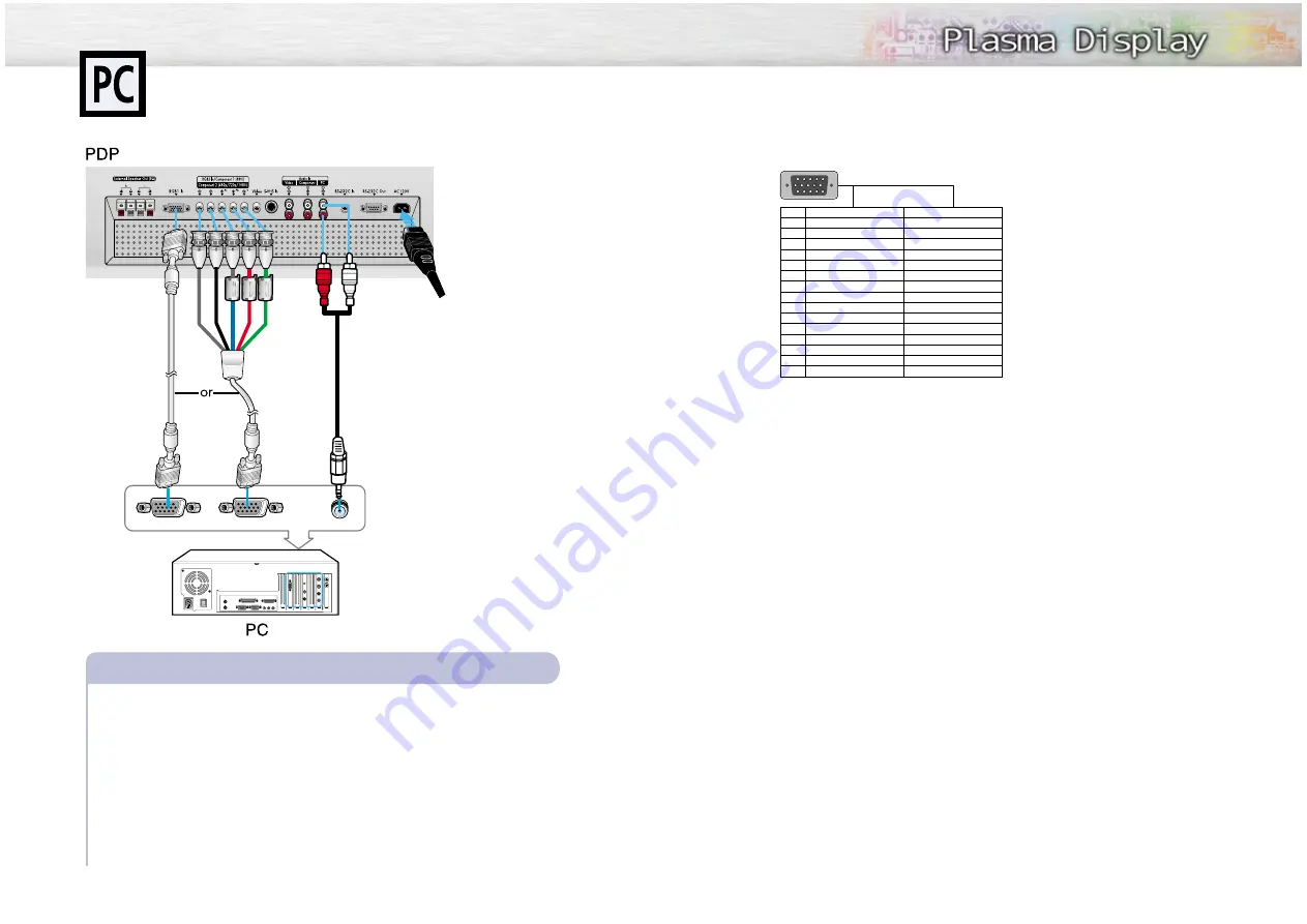
Connecting to a PC

This PDP set is not compatible with Macintosh PC.

45

44

Connect a PC (15pin) or BNC cable between the Video Output jack on the PC and
the RGB1 (15p D-SUB) or RGB2 on the PDP.  
• You can attach the 

Ferrite Cores

to each jack of the BNC cable. 

• For an explanation of Component video, see your PC owner’s instruction.
Connect a Audio cable between the Audio Output jack on the PC and the Audio Input (PC)
on the PDP.  

To watch the PC screen:

1. Turn on PDP and press the RGB button to select the PC mode.
2. Turn on PC and check for PC system requirements.

(Refer to pages 46 and 47 for PC system requirements.)

3. Adjust the PC screen. (Refer to page 48.)

Connecting a PC to the PDP

PC (15pin) 

Cable

BNC 

Cable

Audio Cable

1

2

3

4

5

6

7

8

10

11

12

13

14

15

Pin No.

PC 

IN

Red 

(R)

Green

 (G)

Blue

 (B)

Grounding

Grounding

 (DDC)

Red 

(R) 

Grounding

Green

 (G) 

Grounding

Blue

 (B) 

Grounding

Reserved

Sync Grounding

Grounding

Data

 (DDC)

Horizontal sync.

Vertical sync.

Clock

 (DDC)

PC 

OUT

Red 

(R)

Green

 (G)

Blue

 (B)

Grounding

Grounding

 (DDC)

Red 

(R) 

Grounding

Green

 (G) 

Grounding

Blue

 (B) 

Grounding

Reserved

Sync Grounding

Grounding

Data

 (DDC)

Horizontal sync.

Vertical sync.

Clock

 (DDC)

1
2
3
4
5
6
7
8
9

10
11
12
13
14
15

Power Plug

1

2

Summary of Contents for HPL5025M

Page 1: ...AA68 02166A ENG Owner s Instructions HPL5025M...

Page 2: ...that there is adequate ventilation and that you ve followed the manufacturer s instructions for mounting Operate your Monitor only from the type of power source indicated on the marking label If you...

Page 3: ...oducts with the CE Marking comply with both the EMC Directive 89 336 EEC 92 31 EEC 93 68 EEC and the Low Voltage Directive 73 23 EEC issued by the Commission of the European Community Compliance with...

Page 4: ...age 60 Setting the Multi Control 61 Using the Key Lock 62 Setting up Your Remote Control 63 Appendix Troubleshooting 66 Care and Maintenance 67 Specifications 68 7 User Instructions Screen Image reten...

Page 5: ...P L A S M A D I S P L A Y P A N E L Setup Your New Plasma Display Panel 10 Remote Control Buttons 12 Wall Installation Instructions 14 Turning the PDP On and Off 18...

Page 6: ...put 1 jack 15pin Connect to the video output jack on your PC RGB Input 2 Component Video Input jacks H V R G B Y Pb Pr RGB input2 Component video input jacks are BNC connectors Video Input jack Connec...

Page 7: ...de button Adjust the PDP picture by selecting on of the preset fac tory settings or select your personal customized pic ture settings Aspect button Press to change the screen size Mode button Selects...

Page 8: ...ot install the PDP on any place other than vertical walls 2 To protect the performance of the PDP and prevent troubles avoid the following Do not install next to smoke and fire detectors Do not instal...

Page 9: ...y 5 Insert the bolts dish type washers and insulation holder into the six screw holes as shown in the following figure Bolt Insulation holder 6 Put the insulation rubber point protruding from the rear...

Page 10: ...e easy to use menu system that appears on the PDP screen This system makes it con venient and fast to use features on the PDP Your PDP also lets you display the status of many of your PDP s features V...

Page 11: ...P L A S M A D I S P L A Y P A N E L Connection Connecting Speakers Receiver Connecting Speakers 22 Connecting a VCR Cable Box 23 Connecting a DVD Set Top Box 24...

Page 12: ...utput jack on the VCR Cable box and the Video Input jack on the PDP For better video you can use a S Video cable You can attach the Ferrite Cores supplied to the both jacks of the Video cable Simply s...

Page 13: ...e PDP You can attach the Ferrite Cores supplied to the both jacks of the Video cable Simply set the Ferrite Cores right under the jacks Connect an Audio cable between the Audio Output jack on the DVD...

Page 14: ...Exit 26 1 Press the Menu button then press the joystick to enter 2 Move the joystick left or right to select the Custom You will also see the items Contrast Brightness Sharpness Color and Tint 3 Move...

Page 15: ...jacks 4 Press the Menu button to exit PIP Select On Locate Source Move Adjust Exit PIP Select On Locate Source Move Adjust Exit PIP VIDEO S VIDEO COMPONENT Move Adjust Exit 28 Selecting the PIP Screen...

Page 16: ...Zoom2 Stretch 4 3 When you press the Aspect button on the remote control the PDP s screen mode should appear in sequence The screen displays in this order Wide Panorama Zoom1 Zoom2 Stretch 4 3 Note If...

Page 17: ...the Still button on the remote control to freeze a mov ing picture into a still one Press again to cancel P L A S M A D I S P L A Y P A N E L Sound Control Customizing the Sound 34 Using Automatic Sou...

Page 18: ...Press the Menu button Move the joystick up or down to select the AUDIO then press the joystick to enter 2 Move the joystick left or right to select the Custom You will also see the items Treble Bass B...

Page 19: ...p or down to select the AUDIO then press the joystick to enter 2 Move the joystick up or down to select the Surround then move the joystick left or right to select the Concert Hall or Stadium 3 Press...

Page 20: ...ff 1 Press the Menu button Move the joystick up or down to select the TIME then press the joystick to enter 2 Move the joystick left or right to select hour then move the joystick up or down to select...

Page 21: ...ve the joystick up or down to select the TIME then press the joystick to enter 2 Move the joystick up or down to select the On time then move the joystick left or right 3 Move the joystick left or rig...

Page 22: ...eration Connecting to a PC 44 Adjusting the PC Screen 48 Changing the Position of the Image 49 Changing the Size of the Image 50 Enlarge of the Image Zoom 51 Move Expanded Picture 52 Picture Quality A...

Page 23: ...the PDP You can attach the Ferrite Cores to each jack of the BNC cable For an explanation of Component video see your PC owner s instruction Connect a Audio cable between the Audio Output jack on the...

Page 24: ...37 861 37 861 31 469 37 927 31 469 37 861 37 500 43 269 35 156 37 879 48 077 46 875 53 674 48 363 56 476 60 023 68 677 67 500 63 981 79 976 N N P P P N N N N N P P P P P N N P P P P P P P N N N N N N...

Page 25: ...g the R G B Preset Press the RGB button to select the PC mode 1 Press the Menu button then press the joystick to enter 2 Move the joystick up or down to select the Color Control then move the joystick...

Page 26: ...Miscellaneous Move Adjust Exit Zoom 5 Panning Move Adjust Exit 50 Preset Press the RGB button to select the PC mode 1 Press the Menu button Move the joystick up or down to select the SETUP then press...

Page 27: ...t Exit 52 Preset Press the RGB button to select the PC mode 1 Press the Menu button Move the joystick up or down to select the SETUP then press the joystick to enter 2 Move the joystick up or down to...

Page 28: ...ning Image Lock Miscellaneous Move Adjust Exit Auto Adjustment Frequency 0 Phase 0 Move Adjust Exit Phase 50 54 Frequency Adjustment Preset Press the RGB button to select the PC mode 1 Press the Menu...

Page 29: ...er management system saves energy by switching your monitor into a low power mode when it has not been used for a certain amount of time This power management system operates with a VESA DPMS complian...

Page 30: ...Selecting a Menu Language 60 Setting the Multi Control 61 Using the Key Lock 62 Setting up Your Remote Control 63 P L A S M A D I S P L A Y P A N E L Function Description...

Page 31: ...Setup operates by using only the joystick or channel up down buttons 4 Move the joystick up or down to select the ID Input The ID Input operates by using only the numeric buttons 5 Enter ID Input and...

Page 32: ...mote control Your VCR or Cable box DVD players should turn on if your remote is set up correctly If your VCR or Cable box DVD players does not turn on after set up repeat steps 2 3 and 4 but try one o...

Page 33: ...P L A S M A D I S P L A Y P A N E L Appendix Troubleshooting 66 Care and Maintenance 67 Specifications 68 64 Remote Control Codes VCR Codes Cable Box Codes DVD Codes...

Page 34: ...ed on Adjust the Brightness or Contrast settings Adjust the Size settings The PDP is overheated Power off the PDP and cool it for a while The cooling fan of the PDP may have a problem Contact an autho...

Page 35: ...7 58 W X 3 50 D X 28 50 H inches 54 W X 31 5 D X 220 H mm 2 13 W X 1 24 D X 8 66 H inches 42kg 92 59lbs 150g including batteries 0 33lbs 120V 60 Hz 540 Watts 1106 5 H x 622 V mm 43 56 x 24 49 RGB1 MIN...

Page 36: ...Memo 71 70 Memo...

Reviews: