


KONA LH Capture, Display, Convert v14.3 20 www.aja.com
AJA Control Panel User Interface
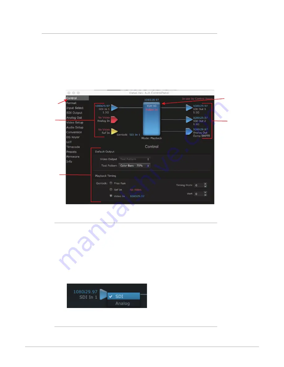
The AJA Control Panel user interface includes a visual block diagram of the unit’s
current configuration. The current status, input and output settings, and many
other details are depicted in the color-coded block diagram. Below this block
diagram are various controls for changing operating parameters, which will vary
depending on which function screen has been selected.
The left side of the AJA Control Panel provides a navigation list of available
function screens. Clicking on a link (or alternatively, a related element in the block
diagram) displays a function screen corresponding to that topic.
Figure 8. AJA Control Panel, Block Diagram and Controls
Inputs
Framebuffer
Format
(Primary)
Outputs
Currently
Selected
Function
Screen
Parameter
Controls
Block Diagram Area
The top block diagram area of the Control Panel screen is a visual representation
of the processing, if any, that’s currently occurring, including inputs/outputs,
reference source, and system status. Lines between inputs, the framebuffer, and
outputs, show a video path. Where there are no lines, there is no connection; this
can be because an input or output isn’t selected in the Input Select menu. The
lines will also show whether the outputs are video or video + key.
You can click any of the function screen selection links in the left column to view
its current settings or click on an icon to call up its related settings screen. You can
also right-click or Control-click to see context-sensitive information and choices.
Figure 9. Context Sensitive Menu
Color Meanings
All items in the AJA Control Panel block diagram are color-coded to show what is
happening in real time. This applies to both icons and text. These colors indicate:


